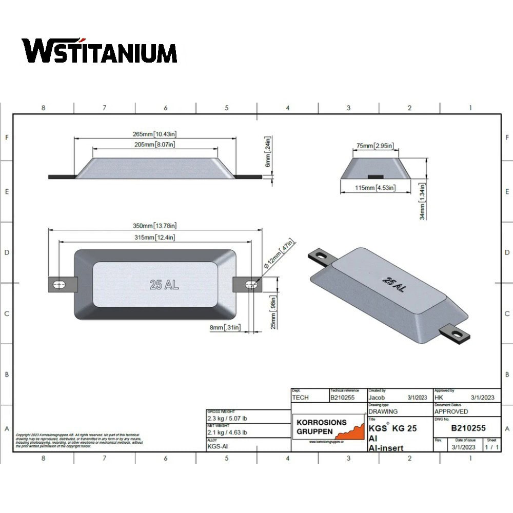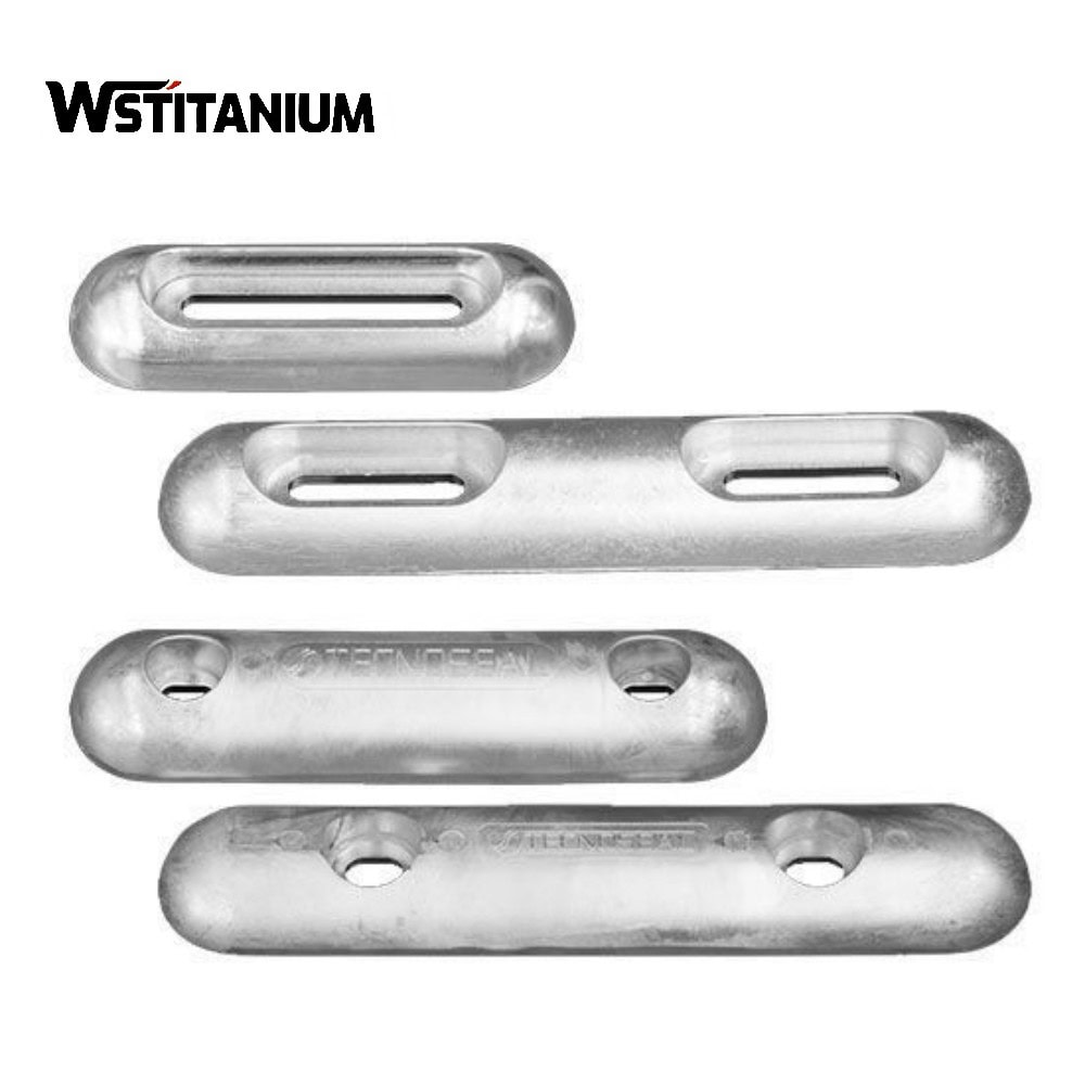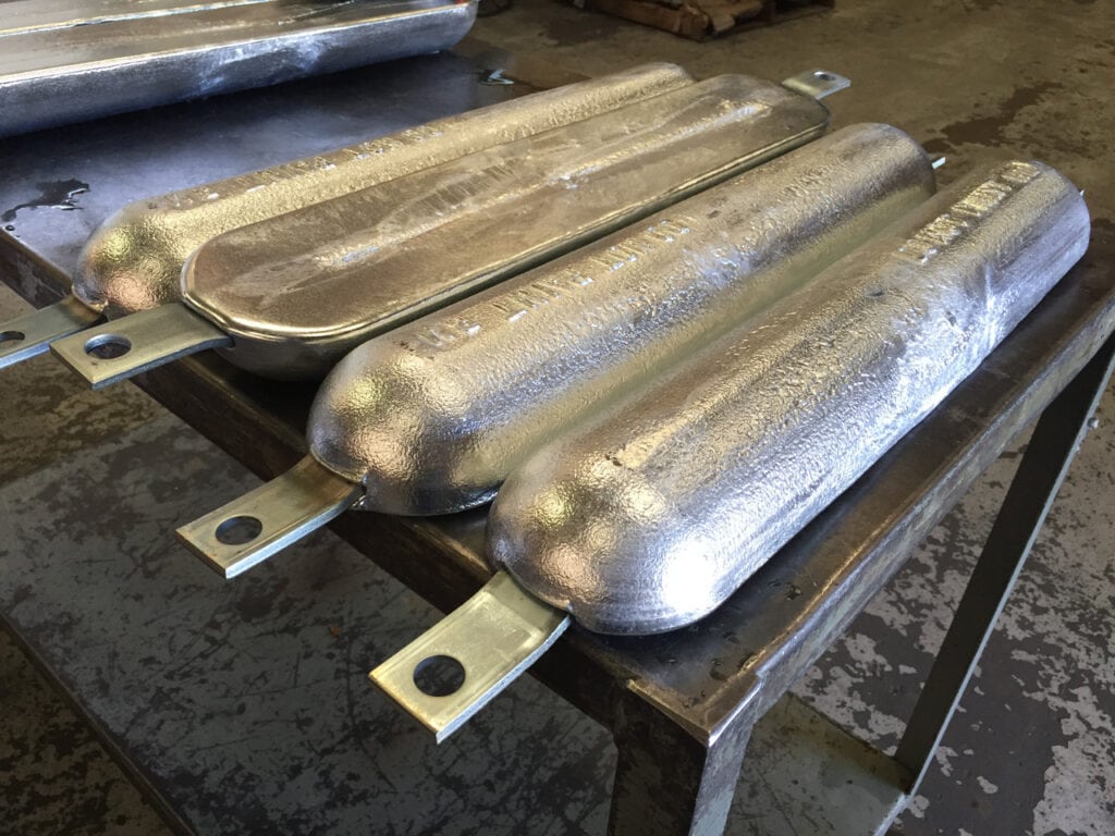
Aluminum Sacrificial Anode
Seawater, brackish water, low resistivity waters; merchant ships, fishing boats, coastal ships.
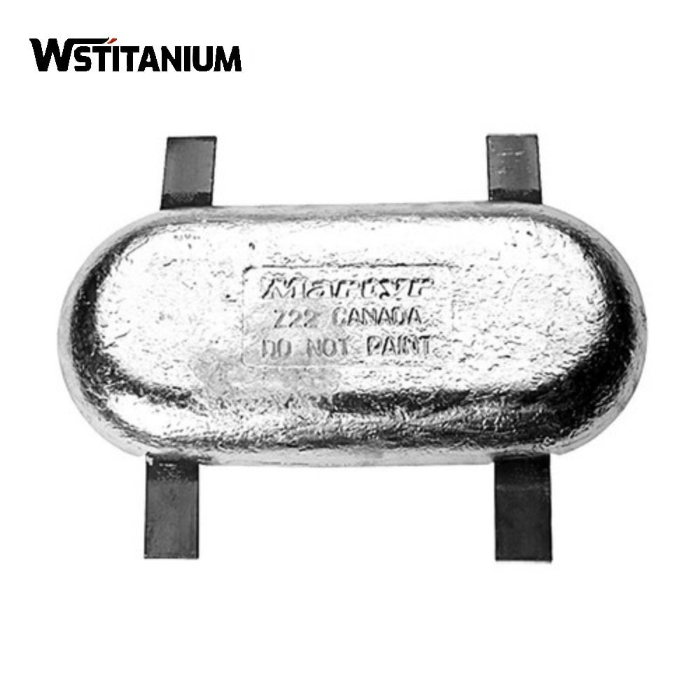
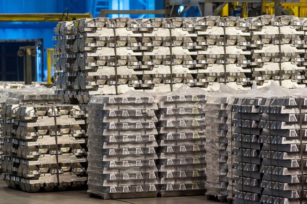
Zinc Sacrificial Anode
High-salinity seawater; ocean-going ships, deep-sea operation platforms.
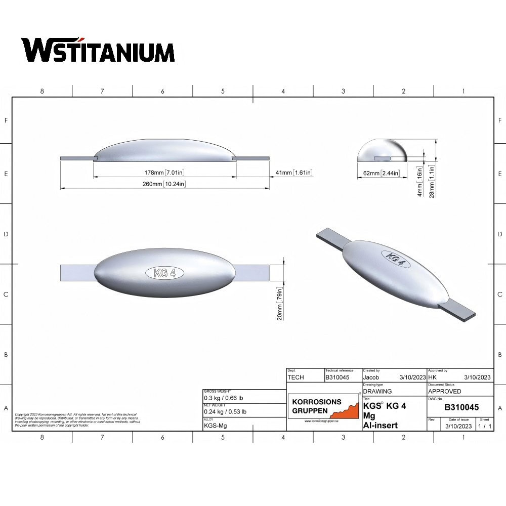
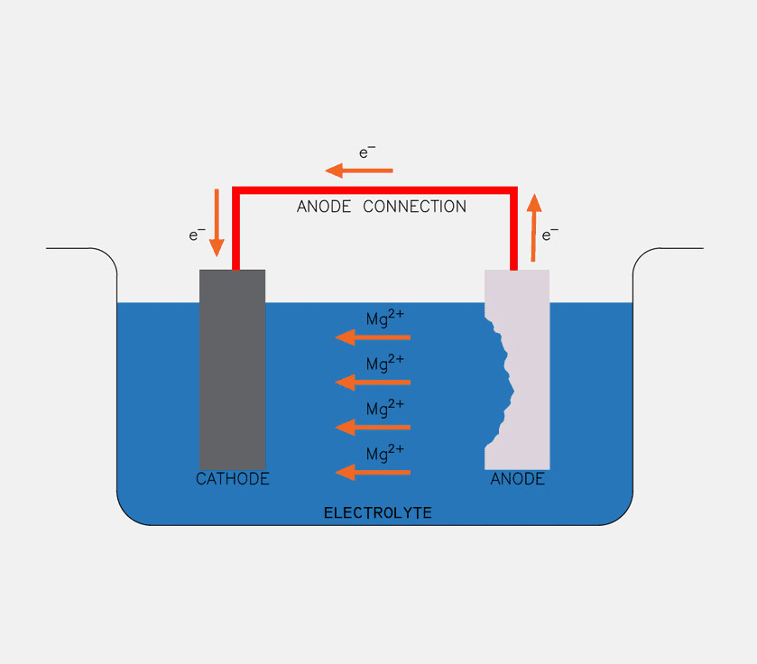
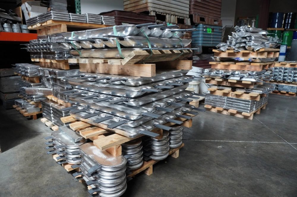
Magnesium Sacrificial Anode
Fresh water, high-resistivity inland waters; inland river ships, lake operation ships.