The Ultimate Guide to Thermal Evaporation Coatings
Thermal evaporation coating is one of the most basic and widely used thin film preparation methods in physical vapor deposition (PVD). Since its birth in the early 20th century, it has played an irreplaceable role in many fields such as optics, electronics, materials science, aerospace, etc.
- Low Cost
- Good Film Uniformity
- Higher Film Deposition Rate
- Strong Film-Substrate Bonding
Wstitanium Workshop
Our Powerful Facilities
Everything You Should Know About Thermal Evaporation Coating
Thermal evaporation coating is one of the classic and mature physical vapor deposition technologies. With its clear principles, simple equipment, and stable film quality, it has always maintained strong vitality in the past 100 years of development. This blog explains the thermal evaporation coating system, from core principles to practical applications, and provides a reference for research in related fields.
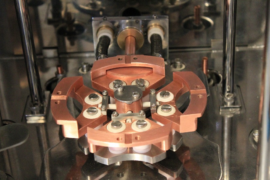
Thermal evaporation coating is to heat the material to the evaporation temperature through specific heating in a high vacuum environment, so that it changes from solid to gas. The evaporated atoms or molecules are ejected to the substrate surface in a linear motion in a vacuum, and condense and deposit on the substrate. The atoms or molecules of the coating material shuttle freely in the form of gas, and finally arrange in an orderly manner on the surface of the substrate to build a layer of film with specific functions and performance.
Compared with other coating technologies, evaporation coating has unique advantages and characteristics. Its equipment is relatively simple, the cost is relatively low, and it is competitive in large-scale production. Evaporation coating achieves a high deposition rate. In a high vacuum environment, the introduction of impurities is effectively avoided, thereby obtaining high-purity film.
Principle of Thermal Evaporation Coating
In thermal evaporation coating, the vacuum environment is like a pure stage, providing the necessary conditions for the orderly “performance” of atoms and molecules. When the system is in a high vacuum state, the number of gas molecules is extremely small, which greatly reduces the probability of the evaporated atoms or molecules colliding with other gas molecules during transmission.
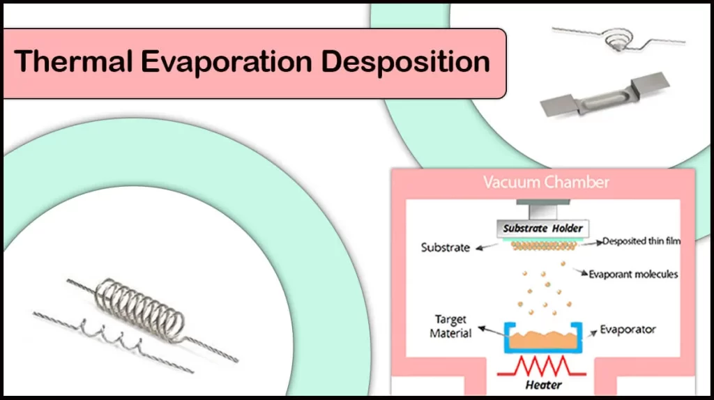
Heating Mechanism
Heating is one of the core links of evaporation coating, which transfers heat to the coating material to gradually increase its temperature. When the temperature reaches the evaporation temperature of the coating material, the material molecules obtain enough energy, overcome the interaction force between molecules, and begin to change from solid to gas, which is evaporation. The transfer and efficiency of heat directly affect the rate and uniformity of evaporation. Taking resistance heating as an example, heat is generated when current passes through the resistance wire. Heat conduction transfers the heat to the coating material. If the temperature distribution of the resistance wire is uneven, it will cause uneven heating of the coating material, thereby affecting the uniformity of evaporation.
Evaporation Mechanism
Evaporation is not a simple material state transition, which involves a complex evaporation dynamic mechanism. According to the molecular motion theory, the evaporation rate of a substance is closely related to factors such as temperature and the vapor pressure of the substance. The higher the vapor pressure of the substance, the faster the evaporation rate. When the coating material is heated, after the molecules on its surface obtain energy, some of the molecules will have enough energy to overcome the surface energy, thereby leaving the material surface and entering the gas phase. As the temperature rises, the number of molecules with this energy increases, and the evaporation rate also accelerates. Evaporation is also affected by factors such as the surface state of the material and the surrounding gas environment. If there are impurities or defects on the surface of the material, it may affect the evaporation behavior of the molecules; and the pressure and composition of the surrounding gas environment will also have a certain impact on the evaporation rate.
Deposition and Film Formation
When the evaporated atoms or molecules enter the vacuum environment in the form of gas, they will move freely in the vacuum to form an atomic flow or a molecular flow. Once these atoms or molecules come into contact with the substrate surface, they will be adsorbed by the substrate surface to form a physical adsorption layer. As the number of adsorbed atoms continues to increase, when a certain critical concentration is reached, tiny crystal nuclei will form on the substrate surface. Once the crystal nuclei are formed, they will continue to adsorb the surrounding atoms and gradually grow. Adjacent crystal nuclei will also fuse with each other to eventually form a continuous film. In the growth of thin films, atomic deposition rate and surface diffusion rate have an important influence on the structure and properties of the film.
If the atomic deposition rate is too fast and the surface diffusion rate is slow, it may lead to more defects and pores in the film; on the contrary, if the surface diffusion rate is fast, the atoms can be fully diffused and arranged in an orderly manner, and a film with a dense structure and excellent performance can be obtained.
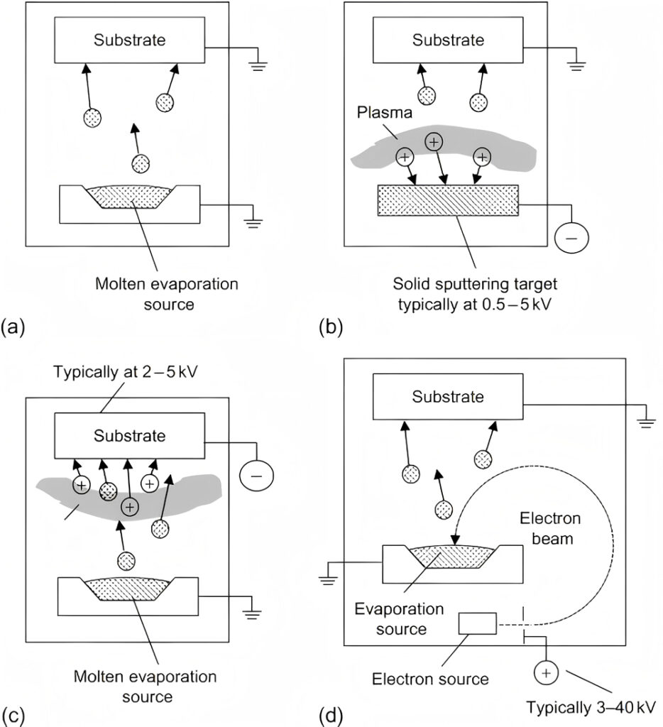
Types of Thermal Evaporation Coating

Laser evaporation coating uses a high-energy-density laser beam to irradiate the coating material, so that it quickly absorbs the laser energy and the temperature rises sharply, thereby achieving instant evaporation. Laser evaporation coating has an extremely high evaporation rate and evaporation efficiency, and completes the deposition of thin films in a short time.
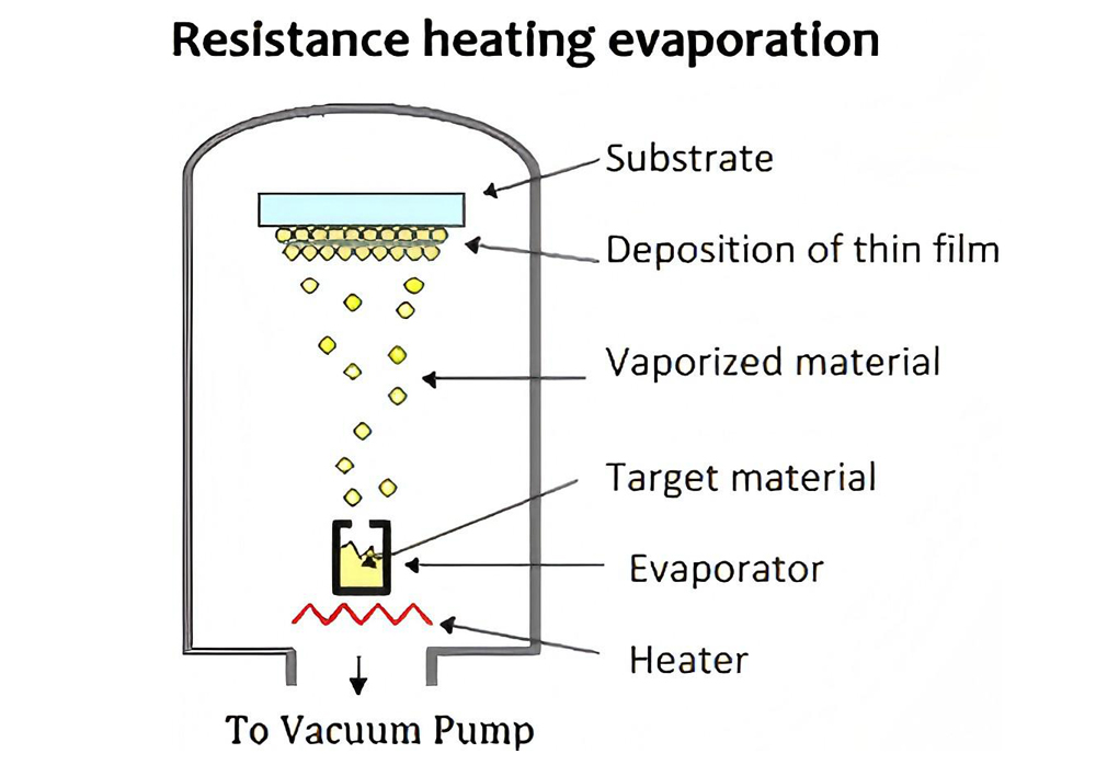
Resistor evaporation coating refers to the process in which the current passes through the resistor material to generate heat, which is transferred to the coating material to reach the evaporation temperature, thereby achieving coating. It is suitable for metals and alloys with low melting points, such as aluminum, silver, and copper.
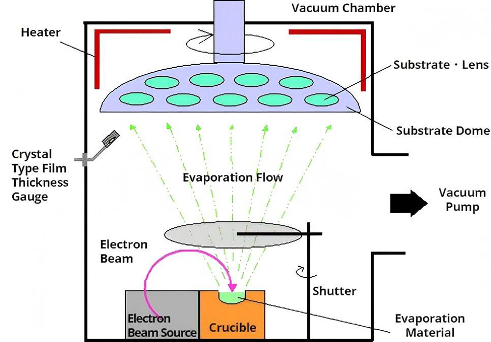
Electron beam evaporation coating uses an electron gun to generate a high-speed electron beam. The electron beam is accelerated under the action of the electric field and focused on the coating material through an electromagnetic lens. The atoms or molecules obtain enough energy to transform from solid to gas to achieve evaporation.
Thermal Evaporation Coating Materials
| Symbol | Melting Point °C | Density | Z-ratio | Temperature °C @ Vapor Pressure (Torr) | Evaporation Method | Crucible Liner | Remarks | ||
| Al | 660 | 2.7 | 1.08 | 677 | 821 | 1010 | eBeam (Xlnt) | TiB2-TiC, TiB2-BN, | High deposition rates possible. Al wets IMCS |
| graphite, BN | |||||||||
| AlSb | 1080 | 4.3 | — | — | — | — | eBeam (fair) | TiB2-BN, BN, C, Al2O3 | Co-evaporation is the best approach |
| AlAs | 1600 | 3.7 | — | — | — | ~1300 | eBeam (poor) | TiB2-BN, BN, Al2O3 | Co-evaporation can work but typically done with MBE |
| AlBr3 | 97 | 3.01 | — | — | — | ~50 | eBeam (poor) | graphite, W | eBeam or thermal evaporation of anhydrous AlBr3 powder |
| Al4C3 | 1400 | 2.36 | — | — | — | ~800 | eBeam (fair) | graphite, W | eBeam evaporation from powder, but CVD is a better approach |
| Al2%Cu | 640 | 2.8 | — | — | — | — | eBeam (fair) | TiB2-TiC, BN | eBeam evaporation of Al-Cu alloys is possible, but sputter deposition is a better approach |
| AlF3 | 1257 | 3.07 | — | 410 | 490 | 700 | eBeam (fair) | graphite, Mo, W | Films tend to be porous, but smooth |
| sublimes | sublimes | ||||||||
| AlN | — | 3.26 | — | — | — | ~1750 | eBeam (fair) | TiB2-TiC, | Reactive evaporation of Al in N2 or ammonia partial pressure |
| sublimes | graphite, BN | ||||||||
| Al2O3 | 2045 | 3.97 | 0.336 | — | — | 1550 | eBeam (Xlnt) | W, graphite | Swept beam with low deposition rates (< 3 Å/sec) |
| Al2%Si | 640 | 2.6 | — | — | — | 1010 | eBeam (fair) | TiB2-TiC, BN | eBeam evaporation of Al-Si alloys is possible, but sputter deposition is a better approach |
| Sb | 630 | 6.68 | — | 279 | 345 | 425 | eBeam (fair) | BN, graphite, Al2O3 | As the deposition rate is increased from 3-5 Å/s the grain size decreases and film coverage improves |
| sublimes | |||||||||
| Sb2Te3 | 619 | 6.5 | — | — | — | 600 | eBeam (fair) | graphite, BN, W | Best results are achieved with powdered source material, relatively high deposition rates can be achieved |
| Sb2O3 | 656 | 5.2 or 5.76 | — | — | — | ~300 | eBeam (good) | BN, Al2O3 | eBeam evaporation from powder or granules |
| sublimes | |||||||||
| Sb2Se3 | 611 | — | — | — | — | — | eBeam (fair) | graphite | Can be co-evaporated with Se to overcome variable stoichiometric effects |
| Sb2S3 | 550 | 4.64 | — | — | — | ~200 | eBeam (good) | Al2O3, Mo, Ta | Films without substrate heating are amorphous, while polycrystalline films form on heated substrates |
| As | 814 | 5.73 | — | 107 | 150 | 210 | eBeam (poor) | Al2O3, BeO, | Sputter deposition is the preferred method for deposition of elemental arsenic |
| graphite | |||||||||
| As2Se3 | 360 | 4.75 | — | — | — | — | eBeam (poor) | Al2O3, quartz | Deposition efficiency increases with deposition rate |
| As2S3 | 300 | 3.43 | — | — | — | ~400 | eBeam (fair) | Al2O3, quartz, Mo | Thin films tend to be richer in As compared to the source material |
| As2Te3 | 362 | — | — | — | — | — | eBeam (poor) | Al2O3, quartz | CVD is the preferred deposition technique for this material |
| Ba | 710 | 3.78 | — | 545 | 627 | 735 | eBeam (fair) | W, Ta, Mo | Reacts with ceramics. Ba evaporation pellets are often shipped with protective coatings which must be removed |
| BaCl2 | 962 | 3.86 | — | — | — | ~650 | eBeam (poor) | W, Mo | Swept beam and slow power ramp to precondition and outgas the source material |
| BaF2 | 1280 | 4.83 | — | — | — | ~700 | eBeam (fair) | W, Mo | Better consistency in refractive index is achieved via CVD |
| sublimes | |||||||||
| BaO | 1923 | 5.72 or 5.32 | — | — | — | ~1300 | eBeam (fair) | Al2O3, quartz | Swept beam and slow power ramp to precondition and outgas the source material |
| BaS | 2200 | 4.25 | — | — | — | 1100 | eBeam (poor) | W, Mo | Sputter deposition is the preferred deposition technique |
| BaTiO3 | Decomposes | 6 | — | Decomposes | eBeam (poor) | W, Mo | BaTiO3 will decompose as single source. Co-evaporate with Ti to maintain Ba/Ti ratio | ||
| Be | 1278 | 1.85 | — | 710 | 878 | 1000 | eBeam (Xlnt) | graphite | Very high deposition rates are possible. Avoid Be powder sources due to toxicity |
| BeCl2 | 440 | 1.9 | — | — | — | ~150 | eBeam (poor) | graphite | CVD is the preferred deposition technique for this material |
| BeF2 | 800 | 1.99 | — | — | — | ~200 | eBeam (fair) | graphite | Avoid powder sources due to toxicity |
| sublimes | |||||||||
| BeO | 2530 | 3.01 | — | — | — | 1900 | eBeam (fair) | graphite, Al2O3 | Thin films can also be produced via reactive evaporation of Be with O2 |
| Bi | 271 | 9.8 | — | 330 | 410 | 520 | eBeam (Xlnt) | Al2O3, graphite | Post deposition thermal annealing significantly enhances film properties. However, vapors are toxic |
| BiF3 | 727 | 8.75 | — | — | — | ~300 | eBeam (poor) | graphite | Sublimes at relatively low temperature, so reasonable vapor pressure can be achieved |
| sublimes | |||||||||
| Bi2O3 | 820 | 8.9 | — | — | — | ~1400 | eBeam (poor) | — | eBeam evaporation from Bi2O3 source is possible, but variations in thin film stoichiometry may occur |
| Bi2Se3 | 710 | 7.66 | — | — | — | ~650 | eBeam (fair) | graphite, quartz | Sputter deposition is preferred, but |
| co-evaporation using Bi and Se sources is possible | |||||||||
| Bi2Te3 | 585 | 7.85 | — | — | — | ~600 | eBeam (fair) | graphite, quartz | Sputter deposition is preferred, but |
| co-evaporation using Bi and Te sources is possible | |||||||||
| Bi2Ti2O7 | — | — | — | Decomposes | eBeam (poor) | graphite, quartz | Decomposes when evaporated. Sputter deposition is preferred, but can be reactively co-evaporated in O2 partial pressure | ||
| Bi2S3 | 685 | 7.39 | — | — | — | — | eBeam (poor) | graphite, W | Can be co-evaporated from Bi and S sources |
| B | 2100 | 2.36 | 0.389 | 1278 | 1548 | 1797 | eBeam (Xlnt) | graphite, W | Can react with graphite and tungsten crucible liners. Requires high power to evaporate |
| sublimes | |||||||||
| B4C | 2350 | 2.5 | — | 2500 | 2580 | 2650 | eBeam (good) | graphite, W | Ion assisted eBeam deposition with Ar can improve film adhesion |
| BN | 2300 | 2.2 | — | — | — | ~1600 | eBeam (poor) | graphite, W | Ion assisted eBeam deposition with N2 produces stoichiometric thin films, but sputter deposition is preferred |
| sublimes | |||||||||
| B2O3 | 460 | 1.82 | — | — | — | ~1400 | eBeam (good) | W, Mo | eBeam evaporation from bulk source material produces stoichiometric thin films |
| B2S3 | 310 | 1.55 | — | — | — | 800 | eBeam (poor) | graphite | — |
| Cd | 321 | 8.64 | — | 64 | 120 | 180 | eBeam (fair) | Al2O3, quartz | Dedicated system is recommended, since Cd can contaminate other purity sensitive depositions |
| CdSb | 456 | 6.92 | — | — | — | — | — | — | — |
| Cd3As2 | 721 | 6.21 | — | — | — | — | eBeam (poor) | quartz | Thin films can be produced by eBeam evaporation from bulk source material, but CVD is a preferred deposition method |
| CdBr2 | 567 | 5.19 | — | — | — | ~300 | — | — | — |
| CdCl2 | 570 | 4.05 | — | — | — | ~400 | — | — | — |
| CdF2 | 1070 | 5.64 | — | — | — | ~500 | — | — | — |
| CdI2 | 400 | 5.3 | — | — | — | ~250 | — | — | CdI2 films have been deposited by thermal evaporation on glass substrates using stoichiometric powders |
| CdO | 900 | 6.95 | — | — | — | ~530 | eBeam (poor) | Al2O3, quartz | Can be produced by reactive evaporation of Cd in partial pressure of O2 or reactive sputtering with O2 |
| CdSe | 1264 | 5.81 | — | — | — | 540 | eBeam (good) | Al2O3, quartz, graphite | eBeam evaporation from bulk source material produces uniform films |
| CdSiO2 | — | — | — | — | — | ~600 | — | — | Reports in the literature of deposition by CVD |
| CdS | 1750 | 4.82 | — | — | — | 550 | eBeam (fair) | Al2O3, quartz, graphite | Substrate heating improves film adhesion. Deposition rates of 15 Å/sec are possible |
| sublimes | |||||||||
| CdTe | 1098 | 6.2 | — | — | — | 450 | eBeam (fair) | Al2O3, quartz, graphite | High quality CdTe thin films on glass substrates at 100°C have been fabricated with eBeam deposition |
| Ca | 842 | 1.56 | — | 272 | 357 | 459 | eBeam (poor) | Al2O3, quartz | Low partial pressure of O2 in the vacuum chamber is required to avoid oxidizing the Ca |
| sublimes | |||||||||
| CaF2 | 1360 | 3.18 | — | — | — | ~1100 | eBeam (Xlnt) | quartz, Ta | Deposition rate of 20 Å/sec are easily achieved with eBeam deposition. |
| Substrate heating improves film quality | |||||||||
| CaO | 2580 | 3.35 | — | — | — | ~1700 | eBeam (poor) | ZrO2, graphite | Forms volatile oxides with W and Mo |
| CaO-SiO2 | 1540 | 2.9 | — | — | — | — | eBeam (good) | quartz | Post deposition thermal annealing at 500°C improves film quality and adhesion |
| CaS | — | 2.18 | — | — | — | 1100 | eBeam (poor) | ZrO2, graphite | Decomposition of CaS bulk source material can be overcome by co- evaporation with S |
| sublimes | |||||||||
| CaTiO3 | 1975 | 4.1 | — | 1490 | 1600 | 1690 | eBeam (poor) | — | Sputter deposition is the preferred method |
| CaWO4 | 1620 | 6.06 | — | — | — | — | eBeam (good) | W, ZrO2 | Substrate heating improves the crystallinity of the deposit |
| C | — | 1.8-2.3 | 0.22 | 1657 | 1867 | 2137 | eBeam (Xlnt) | graphite, W | Better film adhesion results from eBeam evaporation compared to vacuum arc deposition |
| sublimes | sublimes | ||||||||
| Ce | 795 | 8.23 | — | 970 | 1150 | 1380 | eBeam (good) | Al2O3, BeO, | Ce deposits readily oxidize when exposed to air |
| graphite | |||||||||
| CeO2 | 2600 | 7.3 | — | 1890 | 2000 | 2310 | eBeam (good) | graphite, Ta | Stoichiometric films are best achieved using reactive evaporation with O2. |
| sublimes | Substrate heating improves film quality | ||||||||
| CeF3 | 1418 | 6.16 | — | — | — | ~900 | eBeam (good) | Mo, Ta, W | Can be produced using bulk source material. Substrate heating from |
| 150-300°C improves adhesion and film quality | |||||||||
| Ce2O3 | 1692 | 6.87 | — | — | — | — | eBeam (fair) | graphite, Ta | Mixed CeO2-Ce2O3 films can be reduced to Ce2O3 by heating in UHV at 725°C |
| Cs | 28 | 1.87 | — | -16 | 22 | 30 | eBeam (poor) | quartz | — |
| CsBr | 636 | 4.44 | — | — | — | ~400 | — | — | — |
| CsCl | 646 | 3.97 | — | — | — | ~500 | — | — | — |
| CsF | 684 | 3.59 | — | — | — | ~500 | — | — | — |
| CsOH | 272 | 3.67 | — | — | — | ~550 | — | — | — |
| CsI | 621 | 4.51 | — | — | — | ~500 | eBeam (poor) | quartz, Pt | Stoichiometric CsI films are possible from bulk, source material, but good film coverage can be a challenge |
| Na5Al3F14 | — | 2.9 | — | — | — | ~800 | eBeam (poor) | Al2O3 | Stoichiometric chiolite films are difficult to fabricate with eBeam evaporation |
| Cr | 1890 | 7.2 | 0.305 | 837 | 977 | 1157 | eBeam (good) | W, graphite | Films are very adherent. High deposition rates possible, but uniformity can be an issue |
| sublimes | |||||||||
| CrB | 2760 | 6.17 | — | — | — | — | — | — | — |
| CrBr2 | 842 | 4.36 | — | — | — | 550 | — | — | — |
| Cr3C2 | 1890 | 6.68 | — | — | — | ~2000 | eBeam (fair) | W | Can be fabricated by co-evaporation of Cr and C |
| CrCl2 | 824 | 2.75 | — | — | — | 550 | — | — | — |
| Cr2O3 | 2435 | 5.21 | — | — | — | ~2000 | eBeam (good) | W | Stoichiometry can be maintained by reactive evaporation in O2 |
| Cr3Si | 1710 | 6.51 | — | — | — | — | — | — | — |
| Cr-SiO | Influenced by Composition | eBeam (good) | W | The quality Cr-SiO cermet films fabricated with eBeam evaporation improves with annealing at 425° C | |||||
| Co | 1495 | 8.9 | — | 850 | 990 | 1200 | eBeam (Xlnt) | Al2O3, BeO, | Pellets or powder both work well as source material |
| graphite | |||||||||
| CoBr2 | 678 | 4.91 | — | — | — | 400 | — | — | — |
| sublimes | |||||||||
| CoCl2 | 740 | 3.36 | — | — | — | 472 | — | — | — |
| sublimes | |||||||||
| CoO | 1935 | 5.68 | — | — | — | — | eBeam (fair) | — | CoO can be fabricated by reactive evaporation with O2, but sputter deposition is the preferred fabrication method |
| Cu | 1083 | 8.92 | 0.437 | 727 | 857 | 1017 | eBeam (Xlnt) | Al2O3, Mo Ta, | Poor adhesion on most substrates. Use thin adhesion layer of Cr or Ti |
| graphite | |||||||||
| CuCl | 422 | 3.53 | — | — | — | ~600 | eBeam (poor) | quartz | Stoichiometric CuCl films have been produced from pellets and powder source material |
| Cu2O | 1235 | 6 | — | — | — | ~600 | eBeam (good) | graphite, Al2O3, Ta | Thin films have been fabricated from stoichiometric Cu2O powder |
| sublimes | |||||||||
| CuS | 1113 | 6.75 | — | — | — | ~500 | — | — | — |
| sublimes | |||||||||
| Na3AlF6 | 1000 | 2.9 | — | 1020 | 1260 | 1480 | eBeam (good) | W, graphite | Good films can be fabricated using pellets or powder source material. |
| Dy | 1409 | 8.54 | — | 625 | 750 | 900 | eBeam (good) | W | Quality thin films can be fabricated from bulk source material |
| DyF3 | 1360 | 6 | — | — | — | ~800 | eBeam (good) | W, Ta | Bulk source material is available in pellets and powder form |
| sublimes | |||||||||
| Dy2O3 | 2340 | 7.81 | — | — | — | ~1400 | eBeam (fair) | W | Thin films have been fabricated from bulk source material |
| Er | 1497 | 9.06 | 0.74 | 650 | 775 | 930 | eBeam (good) | W, Ta | — |
| sublimes | |||||||||
| ErF2 | 1380 | 6.5 | — | — | — | ~950 | — | — | — |
| Er2O3 | 2400 | 8.64 | — | — | — | ~1600 | eBeam (fair) | W | Reactive evaporation of bulk material in O2 atmosphere maintains stoichiometry. |
| Eu | 822 | 5.26 | — | 280 | 360 | 480 | eBeam (fair) | Al2O3 | — |
| sublimes | |||||||||
| EuF2 | 1380 | 6.5 | — | — | — | ~950 | — | — | — |
| Eu2O3 | 2400 | 8.64 | — | — | — | ~1600 | eBeam (good) | W | Reactive evaporation of Eu2O3 powder or granules in O2 atmosphere maintains stoichiometry. |
| EuS | — | 5.75 | — | — | — | — | eBeam (good) | W | eBeam evaporation of EuS powder in UHV (10-8 torr base vacuum) has been reported in the literature |
| Gd | 1312 | 7.89 | — | 760 | 900 | 1175 | eBeam (Xlnt) | Al203, W | eBeam evaporation of Gd directly from the water cooled Cu hearth has been reported |
| Gd2O3 | 2310 | 7.41 | — | — | — | — | eBeam (fair) | Al203, W | Reactive evaporation of Gd2O3 pellets in O2 maintains thin film stoichiometry. Refractive index increases with substrate heating |
| Ga | 30 | 5.9 | — | 619 | 742 | 907 | eBeam (good) | graphite, Al2O3, BeO, quartz | Alloys with refractory metals |
| GaSb | 710 | 5.6 | — | — | — | — | eBeam (fair) | W, Ta | eBeam evaporation from bulk source material is possible |
| GaAs | 1238 | 5.3 | — | — | — | — | eBeam (good) | graphite, W | Film quality is improved with ion assisted evaporation |
| GaN | — | 6.1 | — | — | — | ~200 | eBeam (fair) | graphite, Al2O3, BeO, quartz | Reactive evaporation of Ga in 10-3 N |
| sublimes | 2 | ||||||||
| Ga2O3 | 1900 | 5.88 | — | — | — | — | eBeam (fair) | graphite, W | Reactive evaporation of Ga2O3 in O2 partial pressure maintains stoichiometry |
| GaP | 1540 | 4.1 | — | — | 770 | 920 | eBeam (fair) | quartz, W | Co-evaporation of Ga and P has been reported |
| Ge | 937 | 5.35 | 0.516 | 812 | 957 | 1167 | eBeam (Xlnt) | Al2O3, quartz, graphite, Ni | Uniform films achieved with slow power ramp and swept beam |
| Ge3N2 | 450 | 5.2 | — | — | — | ~650 | eBeam (poor) | — | Sputtering is the preferred method of fabrication |
| sublimes | |||||||||
| GeO2 | 1086 | 6.24 | — | — | — | ~625 | eBeam (good) | graphite, Al2O3, quartz | GeO2 stoichiometry can be maintained by reactive evaporation of bulk source material in O2 |
| GeTe | 725 | 6.2 | — | — | — | 381 | — | — | — |
| Au | 1062 | 19.32 | 0.381 | 807 | 947 | 1132 | eBeam (Xlnt) | W, Al2O3, | Metal spitting can be an issue. Mitigate by slow power ramp with swept beam and low carbon content in source material |
| graphite, BN | |||||||||
| Hf | 2230 | 13.09 | — | 2160 | 2250 | 3090 | eBeam (good) | W | — |
| HfB2 | 3250 | 10.5 | — | — | — | — | — | — | Fabrication of HfB2 films by CVD has been reported |
| HfC | 4160 | 12.2 | — | — | — | ~2600 | — | — | — |
| sublimes | |||||||||
| HfN | 2852 | 13.8 | — | — | — | — | — | — | HfN films have been produced by reactive RF sputtering of Hf in N2 + Ar |
| HfO2 | 2812 | 9.68 | — | — | — | ~2500 | eBeam (fair) | graphite, W | Can be fabricated by reactive evaporation in O2 or using bulk source material. Post process annealing at 500°C improves film quality |
| HfSi2 | 1750 | 7.2 | — | — | — | — | eBeam (fair) | W | HfSi2 thin films have been fabricated by eBeam evaporation of Hf on Si substrates followed by annealing at 750°C for an hour |
| Ho | 1470 | 8.8 | — | 650 | 770 | 950 | eBeam (good) | W | — |
| sublimes | |||||||||
| HoF3 | 1143 | 7.64 | — | — | — | ~800 | — | quartz | — |
| Ho2O3 | 2370 | 8.41 | — | — | — | — | eBeam (fair) | W | Ho2O3 thin films have been fabricated by eBeam evaporation of powdered source material or reactive evaporation of Ho in O2 |
| In | 157 | 7.3 | 0.841 | 487 | 597 | 742 | eBeam (Xlnt) | Mo, graphite, Al2O3 | Wets Cu and W. Mo liner is preferred |
| InSb | 535 | 5.8 | — | 500 | — | ~400 | eBeam (fair) | graphite, W | Thin films fabricated using powdered source material |
| InAs | 943 | 5.7 | — | 780 | 870 | 970 | — | — | Sputter deposition is the preferred thin film fabrication technique |
| In2O3 | 1565 | 7.18 | — | — | — | ~1200 | eBeam (good) | Al2O3 | Thin films have been produced by reactive evaporation of powdered In2O3 in O2 partial pressure. |
| sublimes | |||||||||
| InP | 1058 | 4.8 | — | — | 630 | 730 | eBeam (fair) | graphite, W | Deposits are P rich |
| In2Se3 | 890 | 5.7 | — | — | — | — | eBeam (fair) | graphite, W | Thin films have been fabricated by eBeam evaporation from powdered InSe. Post process annealing improves crystallinity |
| In2S3 | 1050 | 4,9 | — | — | — | 850 | — | — | — |
| sublimes | |||||||||
| In2S | 653 | 5.87 | — | — | — | 650 | — | — | — |
| In2Te3 | 667 | 5.8 | — | — | — | — | — | — | Thin films from co-evaporation of In and Te sources has been reported. |
| In2O3– SnO2 | 1800 | 6.43-7.14 | — | — | — | — | eBeam (good) | graphite | Thin films have been produced from 90% In2O3-10%SnO2 powder in O2 partial pressure. Substrate temperature of 250°C improves electrical conductivity of resulting films |
| Ir | 2459 | 22.65 | — | 1850 | 2080 | 2380 | eBeam (fair) | W | Better uniformity and adhesion can be achieved using sputter deposition |
| Fe | 1535 | 7.86 | 0.349 | 858 | 998 | 1180 | eBeam (Xlnt) | Al2O3, BeO, | Molten Fe will attack and adhere to graphite, severely limiting crucible liner life |
| graphite | |||||||||
| FeBr2 | 689 | 4.64 | — | — | — | 561 | — | — | — |
| FeCl2 | 670 | 2.98 | — | — | — | 300 | — | — | — |
| sublimes | |||||||||
| FeI2 | 592 | 5.31 | — | — | — | 400 | — | — | — |
| FeO | 1425 | 5.7 | — | — | — | — | eBeam (poor) | — | Sputter deposition preferred. |
| Fe2O3 | 1565 | 5.24 | — | — | — | — | eBeam (good) | Al2O3, BeO, | Fe2O3 thin films fabricated by reactive evaporation of Fe in 0.1 Pa O2 partial pressure has been reported |
| graphite | |||||||||
| FeS | 1195 | 4.84 | — | — | — | — | — | — | — |
| La | 920 | 6.17 | — | 990 | 1212 | 1388 | eBeam (Xlnt) | W, Ta | — |
| LaB6 | 2210 | 2.61 | — | — | — | — | eBeam (fair) | — | LaB6 films and coatings are more commonly produced with sputter deposition. |
| LaBr3 | 783 | 5.06 | — | — | — | — | — | — | — |
| LaF3 | 1490 | 6 | — | — | — | 900 | eBeam (good) | Ta, Mo | Ion assisted eBeam evaporation improves film density and adhesion |
| sublimes | |||||||||
| La2O3 | 2250 | 5.84 | — | — | — | 1400 | eBeam (good) | W, graphite | C contamination can occur with graphite crucible liners |
| Pb | 328 | 11.34 | 1.13 | 342 | 427 | 497 | eBeam (Xlnt) | Al2O3, quartz, graphite, W | — |
| PbBr2 | 373 | 6.66 | — | — | — | ~300 | — | — | — |
| PbCl2 | 501 | 5.85 | — | — | — | ~325 | — | — | — |
| PbF2 | 822 | 8.24 | — | — | — | ~400 | — | — | — |
| sublimes | |||||||||
| PbI2 | 502 | 6.16 | — | — | — | ~500 | — | — | — |
| PbO | 890 | 9.53 | — | — | — | ~550 | eBeam (fair) | Al2O3, quartz, W | Stoichiometric PbO thin films can be produced using powdered source material |
| PbSnO3 | 1115 | 8.1 | — | 670 | 780 | 905 | eBeam (poor) | Al2O3, W | Disproportionates |
| PbSe | 1065 | 8.1 | — | — | — | ~500 | eBeam (fair) | Al2O3, graphite | — |
| sublimes | |||||||||
| PbS | 1114 | 7.5 | — | — | — | 550 | eBeam (fair) | Al2O3, quartz | Post deposition annealing at 150°C improves the crystallinity of the films |
| sublimes | |||||||||
| PbTe | 917 | 8.16 | — | 780 | 910 | 1050 | eBeam (poor) | Al2O3, graphite | Films produced from bulk PbTe tend to be Te rich. Sputter deposition is preferred |
| PbTiO3 | — | 7.52 | — | — | — | — | eBeam (fair) | W, Ta | Thin films of PbTiO3 with reactive co- evaporation of PbO powder and TiO2 pellets in O2 partial pressure has been reported |
| Li | 179 | 0.53 | — | 227 | 307 | 407 | eBeam (good) | Ta, Al2O3, BeO | Li films oxidize readily in air |
| LiBr | 547 | 3.46 | — | — | — | ~500 | — | — | — |
| LiCl | 613 | 2.07 | — | — | — | 400 | — | — | — |
| LiF | 870 | 2.6 | — | 875 | 1020 | 1180 | eBeam (good) | W, Mo, Ta, Al2O3 | Rate control important for optical films. Outgas prior to deposition rastered beam |
| LiI | 446 | 4.06 | — | — | — | 400 | — | — | — |
| Li2O | 1427 | 2.01 | — | — | — | 850 | — | — | — |
| Lu | 1652 | 9.84 | — | — | — | 1300 | eBeam (Xlnt) | Al2O3 | — |
| Lu2O3 | 2489 | 9.81 | — | — | — | 1400 | eBeam (fair) | Al2O3 | eBeam evaporation of powdered source material results in stoichiometric films by post deposition rapid thermal anneal in O2 at 400-600°C |
| Mg | 651 | 1.74 | — | 185 | 247 | 327 | eBeam (good) | W, graphite, Al2O3 | Powder is flammable. High deposition rates are possible |
| sublimes | |||||||||
| MgAl2O4 | 2135 | 3.6 | — | — | — | — | — | — | eBeam deposition from MgAl2O4 powder has been reported |
| MgBr2 | 700 | 3.72 | — | — | — | ~450 | — | — | — |
| MgCl2 | 708 | 2.32 | — | — | — | 400 | — | — | — |
| MgF2 | 1266 | 2.9-3.2 | — | — | — | 1000 | eBeam (Xlnt) | Al2O3, graphite, Mo | Best optical properties result from substrate heating at 300°C and a deposition rate of ≤ 5 Å/sec |
| MgI2 | 700 | 4.24 | — | — | — | 200 | — | — | — |
| MgO | 2800 | 3.58 | — | — | — | 1300 | eBeam (good) | Al2O3, graphite | Stoichiometric films result from reactive evaporation in partial pressure of 10-3 torr O2 |
| Mn | 1244 | 7.2 | — | 507 | 572 | 647 | eBeam (good) | W, Al2O3, BeO | — |
| sublimes | |||||||||
| MnBr2 | 695 | 4.38 | — | — | — | 500 | — | — | — |
| MnCl2 | 650 | 2.98 | — | — | — | 450 | — | — | — |
| MnO2 | 535 | 5.03 | — | — | — | — | eBeam (poor) | W, Mo, Al2O3 | Stoichiometric thin films have been produced by reactive evaporation of Mn powder in 10-3 torr O |
| 2 | |||||||||
| MnS | 1615 | 3.99 | — | — | — | 1300 | — | — | — |
| Hg | -39 | 13.55 | — | -68 | -42 | -6 | — | — | Toxic, not recommended for evaporation processes |
| HgS | 8.1 | — | — | — | 250 | eBeam (poor) | Al2O3 | Toxic and decomposes, not recommended for evaporation processes | |
| sublimes | sublimes | ||||||||
| Mo | 2610 | 10.22 | — | 1592 | 1822 | 2117 | eBeam (Xlnt) | graphite, W | Films are smooth, hard and adherent |
| MoB2 | 2100 | 7.12 | — | — | — | — | — | — | — |
| Mo2C | 2687 | 9.18 | — | — | — | — | — | — | Thin films of Mo2C by sputter deposition and CVD have been reported |
| MoS2 | 1185 | 4.8 | — | — | — | ~50 | — | — | Fabrication of MoS2 by CVD has been reported |
| MoSi2 | 2050 | 6.3 | — | — | — | ~50 | — | — | MoSi2 films have been produced by sputter deposition |
| MoO3 | 795 | 4.7 | — | — | — | ~900 | eBeam (fair) | Al2O3, graphite, BN, Mo | Substrate heating improves film crystallinity |
| Nd | 1024 | 7 | — | 731 | 871 | 1062 | eBeam (Xlnt) | Al2O3, Ta | — |
| NdF3 | 1410 | 6.5 | — | — | — | ~900 | eBeam (good) | W, Mo, Al2O3 | Substrate heating at 360°C improved film quality |
| Nd2O3 | 2272 | 7.24 | — | — | — | ~1400 | eBeam (good) | W, Ta | Films may be oxygen deficient. Refractive index increases with increasing substrate temperature |
| Ni | 1453 | 8.91 | 0.331 | 927 | 1072 | 1262 | eBeam (Xlnt) | Al2O3, BeO, W, | Differential thermal expansion between Ni and graphite can cause graphite crucible liners to crack on cooling |
| graphite | |||||||||
| NiBr2 | 963 | 4.64 | — | — | — | 362 | — | — | — |
| sublimes | |||||||||
| NiCl2 | 1001 | 3.55 | — | — | — | 444 | — | — | — |
| sublimes | |||||||||
| NiO | 1990 | 7.45 | — | — | — | ~1470 | eBeam (good) | Al2O3, W | Substrate temperature of 125°C improves film adhesion and quality. Use of NiO powder as source material mitigates spitting |
| Nb (Cb) | 2468 | 8.55 | — | 1728 | 1977 | 2287 | eBeam (Xlnt) | graphite | Ion assisted eBeam evaporation modifies Nb film stress from tensile to compressive at a substrate temperature of 400°C |
| NbB2 | 3050 | 6.97 | — | — | — | — | — | — | — |
| NbC | 3800 | 7.82 | — | — | — | — | eBeam (fair) | graphite | NbC thin films on Ti has been reported |
| NbN | 2573 | 8.4 | — | — | — | — | eBeam (fair) | graphite, W | NbN films have been fabricated using reactive evaporation and reactive sputtering in N2. NbN films by ion assisted evaporation have also been reported |
| NbO | — | 6.27 | — | — | — | 1100 | — | — | — |
| Nb2O5 | 1530 | 4.47 | — | — | — | — | — | — | Nb2O5 films produced by RF magnetron sputtering using a stoichiometric target have been reported |
| NbTe | — | 7.6 | — | — | — | — | — | — | — |
| Nb3Sn | — | — | — | — | — | — | eBeam (Xlnt) | graphite, Ta | Films produced by co-evaporation of Nb and Sn have been reported. Substrate heating improves film homogeneity |
| Nb2O3 | 1780 | 7.5 | — | — | — | — | — | — | — |
| Os | 1700 | 22.5 | — | 2170 | 2430 | 2760 | — | — | — |
| Pd | 1550 | 12.4 | — | — | — | 1192 | eBeam (Xlnt) | W, Al2O3, | Susceptible to metal spitting. Mitigate with slow power ramp and longer soak before deposition |
| graphite | |||||||||
| PdO | 870 | 8.31 | — | — | — | 575 | eBeam (poor) | Al2O3 | Decomposes |
| P | 41.4 | 1.82 | — | 327 | 361 | 402 | eBeam (poor) | Al2O3 | Reacts violently in air |
| Pt | 1769 | 21.45 | 0.245 | 1292 | 1492 | 1747 | eBeam (Xlnt) | W, Al2O3, | Low deposition rates (< 5 Å/sec) preferred for film uniformity. Carbon contamination with graphite liners is possible at high power |
| graphite | |||||||||
| Pu | 635 | 19 | — | — | — | — | — | — | Toxic. Radioactive |
| Po | 254 | 9.4 | — | 117 | 170 | 244 | — | — | Toxic. Radioactive |
| K | 64 | 0.86 | — | 23 | 60 | 125 | — | quartz | Highly reactive in air |
| KBr | 730 | 2.75 | — | — | — | ~450 | — | quartz | Use gentle preheat to outgas |
| KCl | 776 | 1.98 | — | — | — | ~510 | eBeam (fair) | Ta, quartz, Mo | Use gentle preheat to outgas |
| KF | 880 | 2.48 | — | — | — | ~500 | eBeam (poor) | quartz | Use gentle preheat to outgas |
| KOH | 360 | 2.04 | — | — | — | ~400 | — | — | — |
| KI | 72 | 3.13 | — | — | — | ~500 | — | — | — |
| Pr | 931 | 6.78 | — | 800 | 950 | 1150 | eBeam (good) | W, graphite, Ta | Pr films will oxidize in air |
| Pr2O3 | 2125 | 6.88 | — | — | — | 1400 | eBeam (good) | W, graphite, ThO2 | Loses oxygen. Reports of Pr2O3 thin films grown by MBE |
| 10月8日 | 10月6日 | 10月4日 | |||||||
| Ra | 700 | 5 | — | 246 | 320 | 416 | — | — | — |
| Re | 3180 | 20.53 | — | 1928 | 2207 | 2571 | eBeam (good) | W, graphite | Substrate heating at 600°C improves film properties |
| ReO3 | 297 | 8.2 | — | — | — | ~100 | eBeam (good) | W, graphite | Films produced by reactive evaporation of Re in 10-3 torr O |
| 2 | |||||||||
| Rh | 1966 | 12.41 | — | 1277 | 1472 | 1707 | eBeam (good) | W, graphite | — |
| Rb | 38.5 | 1.47 | — | -3 | 37 | 111 | — | quartz | — |
| RbCl | 715 | 2.76 | — | — | — | ~500 | — | quartz | — |
| RbI | 642 | 3.55 | — | — | — | ~400 | — | quartz | — |
| Ru | 2700 | 12.45 | — | 1780 | 1990 | 2260 | eBeam (poor) | W | Material spits using eBeam. Sputter deposition is preferred |
| Sm | 1072 | 7.54 | — | 373 | 460 | 573 | eBeam (good) | Al2O3 | — |
| Sm2O3 | 2350 | 7.43 | — | — | — | — | eBeam (good) | W | Loses oxygen. Sputter deposition is preferred |
| Sm2S3 | 1900 | 5.72 | — | — | — | — | — | — | — |
| Sc | 1539 | 2.99 | — | 714 | 837 | 1002 | eBeam (Xlnt) | W, Mo, Al2O3 | Alloys with Ta |
| Sc2O3 | 2300 | 3.86 | — | — | — | ~400 | eBeam (fair) | W | Loses oxygen. Films produced by reactive sputtering in O2 have been reported |
| Se | 217 | 4.79 | — | 89 | 125 | 170 | eBeam (good) | W, Mo, graphite, Al2O3 | Toxic. Can contaminate vacuum systems |
| Si | 1410 | 2.42 | 0.712 | 992 | 1147 | 1337 | eBeam (fair) | Ta, graphite, BeO | High deposition rates possible. Molten Si can attack graphite liners limiting crucible liner life |
| SiB6 | — | 2.47 | — | — | — | — | — | — | — |
| SiC | 2700 | 3.22 | — | — | — | 1000 | eBeam (fair) | W | Sputter deposition is the preferred thin film fabrication technique |
| SiO2 | 1610-1710 | 2.2-2.7 | 1 | — | — | ~1025 | eBeam (Xlnt) | Al2O3, Ta, | Swept beam is critical to avoid hole drilling, since the source material will have a shallow melt pool |
| Influenced by composition | graphite, W | ||||||||
| SiO | 1702 | 2.1 | — | — | — | 850 | eBeam (fair) | W, Ta, graphite | Thin films from bulk SiO material has been reported |
| sublimes | |||||||||
| Si3N4 | — | 3.44 | — | — | — | ~800 | — | — | Thin films of Si3N3 by reactive sputter deposition have been reported |
| sublimes | |||||||||
| SiSe | — | — | — | — | — | 550 | — | — | — |
| SiS | — | 1.85 | — | — | — | 450 | — | — | — |
| sublimes | |||||||||
| SiTe2 | — | 4.39 | — | — | — | 550 | — | — | — |
| Ag | 961 | 10.49 | 0.529 | 847 | 958 | 1105 | eBeam (Xlnt) | W, Al2O3, Ta, | Swept beam during melt and focused beam during deposition is recommended for higher deposition rates |
| Mo, graphite | |||||||||
| AgBr | 432 | 6.47 | — | — | — | ~380 | — | — | — |
| AgCl | 455 | 5.56 | — | — | — | ~520 | — | — | — |
| AgI | 558 | 5.67 | — | — | — | ~500 | — | — | Thin films of AgI fabricated by thermal evaporation have been reported |
| Na | 97 | 0.97 | — | 74 | 124 | 192 | — | quartz | Use gentle preheat to outgas. Metal reacts violently in air |
| NaBr | 755 | 3.2 | — | — | — | ~400 | — | — | — |
| NaCl | 801 | 2.16 | — | — | — | 530 | — | — | Thin films of NaCl fabricated by thermal evaporation in Knudsen cells with quartz crucibles have been reported |
| NaCN | 563 | — | — | — | — | ~550 | — | — | — |
| NaF | 988 | 2.79 | — | — | — | ~700 | eBeam (good) | W, Ta, graphite, BeO | Use gentle preheat to outgas. NaF thin films produced from powder source material and 230°C substrate heating have been reported |
| NaOH | 318 | 2.13 | — | — | — | ~470 | — | — | — |
| Sr | 769 | 2.6 | — | 239 | 309 | 403 | eBeam (poor) | graphite, quartz | Wets refractory metals. May react strongly in air |
| SrF2 | 1190 | 4.24 | — | — | — | ~1000 | eBeam (poor) | Al2O3, W, quartz | Thin films of SrF2 produced by eBeam and thermal evaporation have been reported |
| SrO | 2460 | 4.7 | — | — | — | 1500 | eBeam (poor) | Al2O3 | Loses oxygen. Reacts with W and Mo |
| sublimes | |||||||||
| SrS | >2000 | 3.7 | — | — | — | — | — | — | Decomposes |
| S8 | 115 | 2 | — | 13 | 19 | 57 | eBeam (poor) | quartz | Can contaminate vacuum systems |
| Ta | 2996 | 16.6 | — | 1960 | 2240 | 2590 | eBeam (Xlnt) | graphite | High melting point of Ta limits crucible liner selection. High vacuum is required to mitigate oxygen incorporation in films |
| TaB2 | 3000 | 12.38 | — | — | — | — | — | — | — |
| TaC | 3880 | 14.65 | — | — | — | ~2500 | — | — | — |
| TaN | 3360 | 16.3 | — | — | — | — | eBeam (fair) | graphite | Thin films of TaN can be produced by reactive evaporation in 10-3 torr N |
| 2 | |||||||||
| Ta2O5 | 1800 | 8.74 | — | 1550 | 1780 | 1920 | eBeam (good) | graphite, Ta | Swept beam to avoid hole drilling. A thin Ti layer will improve adhesion to the substrate |
| TaS2 | 1300 | — | — | — | — | — | — | — | — |
| Tc | 2200 | 11.5 | — | 1570 | 1800 | 2090 | — | — | — |
| Te | 452 | 6.25 | — | 157 | 207 | 277 | eBeam (poor) | Al2O3, quartz, graphite | Wets refractory metals |
| Tb | 1357 | 8.27 | — | 800 | 950 | 1150 | eBeam (Xlnt) | Al2O3, graphite, Ta | Thin films produced by sputter deposition and thermal evaporation have also been reported |
| TbF3 | 1176 | — | — | — | — | ~800 | — | — | Sputter deposition is preferred |
| Tb2O3 | 2387 | 7.87 | — | — | — | 1300 | — | — | Thin films prepared by pulsed laser deposition have been reported |
| Tb4O7 | 2340 | 7.3 | — | — | — | — | — | — | Annealing of Tb2O3 films at 800°C in air to produce stable Tb4O7 has been reported |
| Tl | 302 | 11.85 | — | 280 | 360 | 470 | eBeam (poor) | Al2O3, quartz, graphite | Thallium and its compounds are very toxic. Wets freely |
| Tlbr | 480 | 7.56 | — | — | — | ~250 | — | — | Thermal evaporation of TlBr thin films has been reported |
| sublimes | |||||||||
| TlCl | 430 | 7 | — | — | — | ~150 | — | — | — |
| sublimes | |||||||||
| TlI | 440 | 7.09 | — | — | — | ~250 | eBeam (poor) | Al2O3, quartz | Low stress thin films can be produced by eBeam evaporation with a substrate temperature of 100°C |
| Tl2O3 | 717 | 9.65 | — | — | — | 350 | — | — | Disproportionates at 850°C to Tl2O |
| Th | 1875 | 11.7 | — | 1430 | 1660 | 1925 | eBeam (Xlnt) | W, Ta, Mo | Toxic and mildly radioactive |
| ThBr4 | — | 5.67 | — | — | — | — | — | — | — |
| sublimes | |||||||||
| ThC2 | 2273 | 8.96 | — | — | — | ~2300 | — | — | — |
| ThO2 | 3050 | 10.03 | — | — | — | ~2100 | eBeam (good) | W | Stable stoichiometric films of ThO2 produced from powdered source material have been reported |
| ThF4 | 1110 | 6.3 | — | — | — | ~750 | eBeam (fair) | Ta, Mo, graphite | Use gentle preheat to outgas. Substrate temperature of 175°C improves film adhesion and quality |
| ThOF2 | 900 | 9.1 | — | — | — | — | eBeam (poor) | W, Ta, Mo, | Does not evaporate stoichiometrically, resulting films are primarily ThF4 |
| graphite | |||||||||
| ThS2 | — | 6.8 | — | — | — | — | — | — | — |
| Tm | 1545 | 9.32 | — | 461 | 554 | 680 | eBeam (good) | Al2O3 | — |
| sublimes | |||||||||
| Tm2O3 | — | 8.9 | — | — | — | 1500 | — | — | Thin films of Tm2O3 by eBeam evaporation and MBE have been reported |
| Sn | 232 | 7.75 | 0.724 | 682 | 807 | 997 | eBeam (Xlnt) | Al2O3, Ta, | High deposition rates possible, but uniformity may suffer. Slow power ramp to mitigate cavitation of melt pool |
| graphite, W | |||||||||
| SnO2 | 1127 | 6.95 | — | — | — | ~1000 | eBeam (Xlnt) | Al2O3, quartz | Substrate temperature above 200°C improves film crystallinity |
| sublimes | |||||||||
| SnSe | 861 | 6.18 | — | — | — | ~400 | — | — | Stoichiometric thin films of SnSe produced by thermal evaporation of powdered source material have been reported |
| SnS | 882 | 5.08 | — | — | — | ~450 | eBeam (poor) | quartz, W | Thin films prepared by eBeam evaporation of SnS powder and reactive co-evaporation of Sn and S have been reported |
| SnTe | 780 | 6.44 | — | — | — | ~450 | eBeam (poor) | quartz | Thin films of SnTe produced with eBeam evaporation at a substrate temperature of 300°C have been reported |
| Ti | 1675 | 4.5 | 0.628 | 1067 | 1235 | 1453 | eBeam (Xlnt) | W, graphite, TiC | Films are very adherent to almost any substrate |
| TiB2 | 2980 | 4.5 | — | — | — | — | — | — | Sputter deposition is the preferred thin film fabrication technique |
| TiC | 3140 | 4.93 | — | — | — | ~2300 | eBeam (fair) | W, graphite | eBeam evaporation of TiC thin films with and without ion beam assistance have been reported |
| TiO2 | 1640 | 4.29 | — | — | — | ~1300 | eBeam (good) | W, graphite, Ta | Stoichiometric thin films of TiO2 have been produced from powder source material and a substrate temperature of 600°C |
| TiO | 1750 | — | — | — | — | ~1500 | eBeam (good) | W, graphite, Ta | Outgas with gentle preheat prior to deposition |
| TiN | 2930 | 5.43 | — | — | — | — | eBeam (good) | W, graphite, TiC | Thin films have been prepared by reactive evaporation of Ti in N2 partial pressure |
| Ti2O3 | 2130 | 4.6 | — | — | — | — | eBeam (good) | W, Ta, graphite | Stoichiometric films have been produced by reactive evaporation of Ti O powder in 2.5 x 10⁻⁴ torr O |
| 2 3 2 | |||||||||
| W | 3410 | 19.3 | 0.163 | 2117 | 2407 | 2757 | eBeam (good) | W | Long, slow preheat is required to condition the source material. Raster the electron beam to avoid hole drilling |
| WB2 | 2900 | 12.75 | — | — | — | — | — | — | — |
| W2C | 2860 | 17.15 | — | 1480 | 1720 | 2120 | eBeam (good) | W, graphite | Thin films prepared by eBeam evaporation of powdered source material have been reported. RF Sputter deposition is widely reported |
| WTe3 | — | 9.49 | — | — | — | — | — | — | — |
| WO3 | 1473 | 7.16 | — | — | — | 980 | eBeam (good) | W | Thin films are most commonly prepared using WO3 powder source material |
| sublimes | |||||||||
| U | 1132 | 19.07 | — | 1132 | 1327 | 1582 | eBeam (good) | W, Mo, graphite | Depleted uranium thin films oxidize easily even in low partial pressure of O2 |
| UC2 | 2260 | 11.28 | — | — | — | 2100 | — | — | — |
| UO2 | 2176 | 10.9 | — | — | — | — | eBeam (fair) | W | Stoichiometric thin films produced by reactive evaporation of depleted uranium in O2 partial pressure have been reported |
| UF4 | ~1000 | — | — | — | — | 300 | — | — | Thin films fabricated by sputter deposition of depleted uranium by F– ions has been reported |
| U3O8 | Decomposes | 8.3 | — | — | — | — | — | — | Thin films produced by reactive sputter deposition of depleted uranium targets in O2 have been reported. |
| UP2 | — | 8.57 | — | — | — | 1200 | — | — | — |
| U2S3 | — | — | — | — | — | 1400 | — | — | — |
| V | 1890 | 5.96 | — | 1162 | 1332 | 1547 | eBeam (Xlnt) | W, graphite, Ta | Wets Mo. eBeam evaporation is preferred |
| VB2 | 2400 | 5.1 | — | — | — | — | — | — | — |
| VC | 2810 | 5.77 | — | — | — | ~1800 | — | — | — |
| VO2 | 1967 | 4.34 | — | — | — | ~575 | eBeam (poor) | W, graphite | Difficult to maintain stoichiometry by eBeam evaporation, sputter deposition is preferred |
| sublimes | |||||||||
| VN | 2320 | 6.13 | — | — | — | — | — | — | — |
| V2O5 | 690 | 3.36 | — | — | — | ~500 | eBeam (good) | W, graphite | Thin films prepared from powdered source material are nearly stoichiometric. Post process annealing at 280° in O2 restores full stoichiometry |
| VSi2 | 1700 | 4.42 | — | — | — | — | — | — | — |
| Yb | 824 | 6.98 | — | 520 | 590 | 690 | eBeam (good) | Al2O3, W, Ta | Store Yb evaporation source material in N2 desiccator to mitigate oxidation |
| sublimes | |||||||||
| YbF3 | 1157 | 8.17 | — | — | — | ~800 | eBeam (fair) | Ta, Mo, W | Preheat slowly and evaporate at |
| ≤ 10Å/sec to mitigate dissociation | |||||||||
| Yb2O3 | 2346 | 9.17 | — | — | — | ~1500 | eBeam (fair) | Al2O3, W, Ta | Thin films produced by reactive evaporation in 8 x 10⁻⁵ torr O have |
| 2 | |||||||||
| sublimes | been reported. | ||||||||
| Y | 1509 | 4.48 | — | 830 | 973 | 1157 | eBeam (Xlnt) | W, Al2O3 | Substrate heating at 300°C improves adhesion and film smoothness |
| Y3Al5O12 | 1990 | — | — | — | — | — | eBeam (good) | W, Al2O3 | Films prepared from powdered source material, typically with dopants. YAG films post deposition annealed at 1100°C in vacuum improves crystallinity |
| YF3 | 1387 | 4.01 | — | — | — | — | eBeam (good) | W, Ta, Mo, Al2O3 | eBeam evaporation at a rate of |
| ≤ 10Å/sec and substrate temperature of 200°C produces crystalline films with good adhesion | |||||||||
| Y2O3 | 2680 | 4.84 | — | — | — | ~2000 | eBeam (good) | graphite, W | eBeam evaporated films can be oxygen deficient, post deposition annealing |
| in 10-3 torr O at 525°C results in | |||||||||
| 2 | |||||||||
| sublimes | stoichiometric films. | ||||||||
| Zn | 419 | 7.14 | 0.514 | 127 | 177 | 250 | eBeam (Xlnt) | W, Al2O3, quartz, graphite | Evaporates well under a wide range of conditions |
| Zn3Sb2 | 546 | 6.3 | — | — | — | — | — | — | — |
| ZnBr2 | 394 | 4.22 | — | — | — | ~300 | — | — | — |
| ZnF2 | 87 | 4.84 | — | — | — | ~800 | eBeam (fair) | quartz, W | Thin films prepared by eBeam evaporation of powdered source material have been reported. Substrate heating at 400°C improved crystallinity |
| Zn3N2 | — | 6.22 | — | — | — | — | — | — | Reactive sputter deposition in N2 has been reported |
| ZnO | 1975 | 5.61 | — | — | — | ~1800 | eBeam (fair) | quartz, W | Quality thin films fabricated using eBeam evaporation at a rate of 8Å/sec and a substrate temperature of 300°C has been reported |
| ZnSe | 1526 | 5.42 | — | — | — | 660 | eBeam (fair) | W, Ta, Mo, | Deposition rate of ≤ 5 Å/sec. Thin films are polycrystalline and a substrate temperature of 300°C improves adhesion and size of crystallites |
| quartz | |||||||||
| ZnS | 1830 | 4.09 | — | — | — | ~800 | eBeam (good) | W, Ta, Mo, | Thin films produced by eBeam evaporation display a preferred (111) orientation and best optical properties result from a 400°C substrate temperature |
| sublimes | quartz | ||||||||
| ZnTe | 1238 | 6.34 | — | — | — | ~600 | eBeam (fair) | W, Ta, Mo, | Stoichiometric thin films produced by eBeam evaporation have good |
| quartz | crystallinity with a substrate temperature of 230°C. Optical properties are thickness dependent | ||||||||
| ZrSiO4 | 2550 | 4.56 | — | — | — | — | — | — | — |
| Zr | 1852 | 6.4 | — | 1477 | 1702 | 1987 | eBeam (Xlnt) | W, quartz | Alloys with W. Thin films oxidize readily |
| ZrB2 | 3040 | 6.08 | — | — | — | — | eBeam (good) | W, quartz | Stoichiometric films prepared by |
| co-evaporation of Zr and B have been reported | |||||||||
| ZrC | 3540 | 6.73 | — | — | — | ~2500 | eBeam (poor) | graphite | Quality thin films of ZrC using pulsed laser deposition have been reported |
| ZrN | 2980 | 7.09 | — | — | — | — | — | — | Thin films of ZrN prepared by N2 ion assisted evaporation of Zr have been reported |
| ZrO2 | 2700 | 5.49 | — | — | — | ~220 | eBeam (good) | W, graphite | Reactive evaporation in 10-3 torr O |
| 2 | |||||||||
| produce as deposited stoichiometric | |||||||||
| films. For eBeam evaporated films, post deposition annealing in O2 restores stoichiometry | |||||||||
| ZrSi2 | 1700 | 4.88 | — | — | — | — | — | — | eBeam evaporated Zr on Si substrates forms ZrSi2 following post deposition thermal annealing at 600°C |
Advantages of Evaporation Coating
High Purity of Thin Film
Evaporation coating is carried out in a high vacuum environment, and the vacuum degree can usually reach 10⁻6Pa or even higher. It greatly reduces the chances of impurities such as oxygen, nitrogen, and water vapor in the air reacting with evaporated atoms or molecules, and also avoids the mixing of impurity particles into the film.
Good Film Uniformity
In evaporation coating, the shape and position of the evaporation source and the movement of the substrate (such as substrate rotation) are reasonably designed to make the evaporated atoms or molecules deposited evenly on the substrate surface. Effectively eliminate the radial difference in film thickness.
Low Cost
Compared with some other thin film preparation technologies (such as chemical vapor deposition, sputtering coating, etc.), the structure of evaporation coating equipment is relatively simple. The cost of manufacturing thin films is relatively low.
Fast Deposition Rate
Evaporation coating can achieve a high deposition rate, which can generally reach a few nanometers to tens of nanometers per second. This means improving efficiency, reducing costs, and reducing the risk of substrate contamination.
Wide Material Adaptability
Evaporation coating technology is applicable to a variety of materials, including metals, non-metals, compounds and some organic materials. This enables evaporation coating technology to meet the diverse needs of thin film materials in different fields.
Strong Bonding Force
By controlling evaporation parameters (such as substrate temperature and evaporation rate), the bonding force between the film and the substrate can be effectively adjusted. Enable atoms to be more closely bonded to the substrate surface.
Disadvantages of Evaporation Coating
Although evaporation coating has many advantages, it also has some inherent disadvantages and limitations in practical applications. These disadvantages limit its application in certain fields to a certain extent.
High Purity of Thin Film
Evaporation coating is carried out in a high vacuum environment, and the vacuum degree can usually reach 10⁻6Pa or even higher. It greatly reduces the chances of impurities such as oxygen, nitrogen, and water vapor in the air reacting with evaporated atoms or molecules, and also avoids the mixing of impurity particles into the film.
Incompatible With High Melting Point Materials
For high melting point materials (such as tungsten, molybdenum, silicon carbide, etc.), the evaporation temperature is extremely high, usually reaching several thousand degrees Celsius. It is difficult to heat these materials to the evaporation temperature.
Large Film Stress
The growth of thin films is affected by many factors (such as the difference in thermal expansion coefficient between the substrate and the film, too fast atomic deposition rate, etc.), resulting in large stress inside the film.
Compound materials are easy to decompose
For organic compound materials, their molecular structure is relatively complex. During heating and evaporation, the chemical bonds between molecules may break, causing the decomposition of organic materials.
Application of Evaporation Coating
Due to its unique advantages, evaporation coating technology has been widely used in many fields and has provided important technical support for the development of various industries.
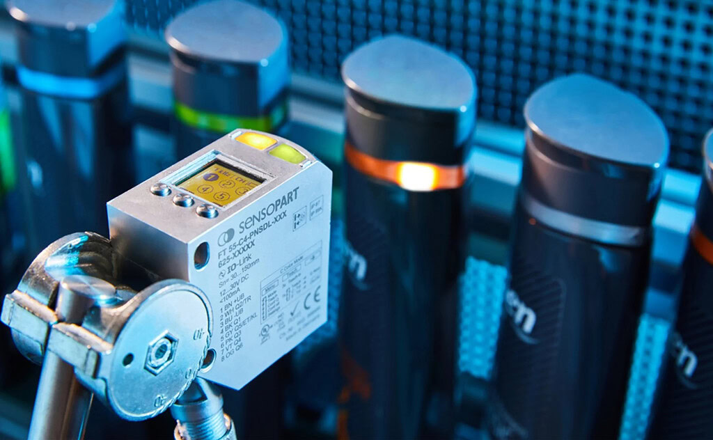
Sensor
The sensitive elements of many sensors (such as temperature sensors, gas sensors, pressure sensors, etc.) require coating technology support. For example, in gas sensors, metal oxide films (such as zinc oxide, tin oxide, etc.) are prepared by evaporation coating. This has sensitive electrical property changes to specific gases, and gas detection can be achieved by detecting its resistance changes. Evaporation coating technology can accurately control the thickness and composition of the film to ensure the sensitivity and stability of the sensor.
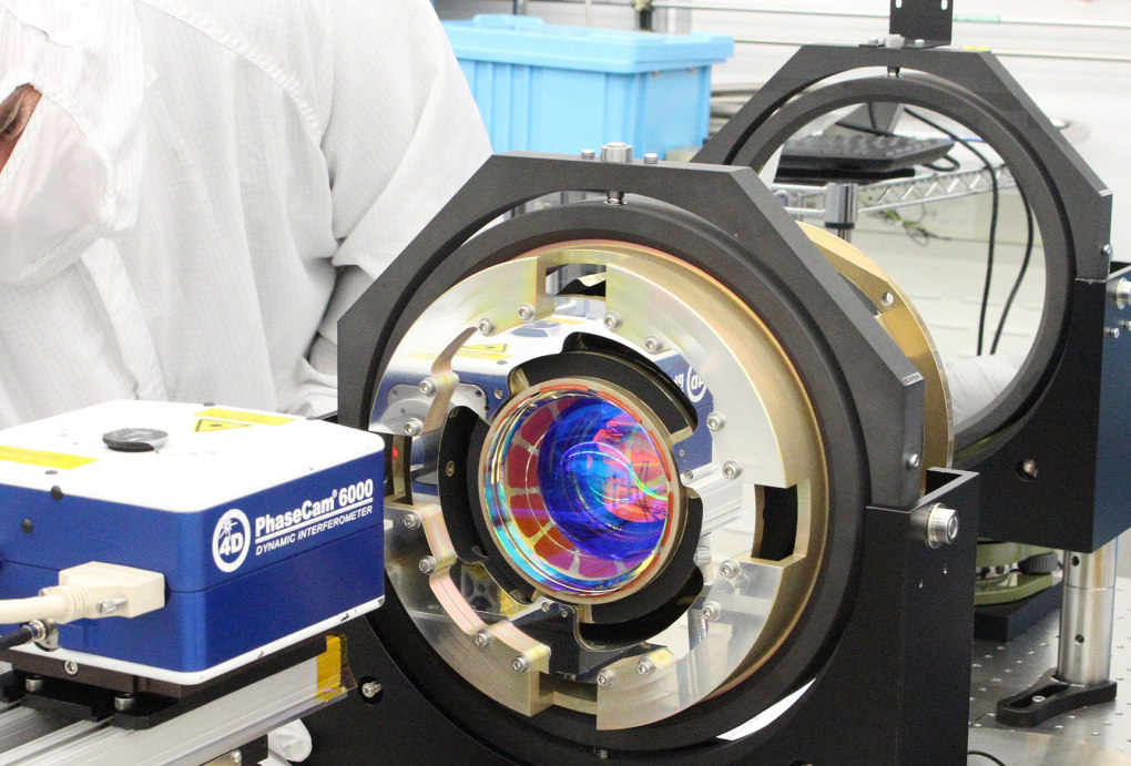
Optics
Evaporation coating technology is widely used in the coating of optical lenses, including anti-reflection film, high reflective film, filter, etc. In storage media such as optical discs (such as CD, DVD, Blu-ray disc), evaporation coating is used to prepare reflective layer and recording layer. The core component of solar cells is semiconductor film that absorbs sunlight and converts it into electrical energy. Evaporation coating technology supports the preparation of various films in solar cells, such as transparent conductive film (ITO film), electrode film, absorption layer film, etc.
Medical
Some medical devices (such as scalpels, syringes, artificial joints, etc.) require surface treatment to improve their performance and biocompatibility. Evaporation coating technology supports the deposition of biocompatible films on the surface of medical devices, such as titanium films, titanium nitride films, etc. Improve the wear resistance, corrosion resistance and biocompatibility of the device.
Conclusion
As an important physical vapor deposition technology, evaporation coating technology has developed for more than a hundred years and has formed a relatively complete theoretical system and diversified process methods. From the early simple resistance evaporation to today’s advanced technologies such as laser evaporation and electron beam evaporation, evaporation coating is expanding its application boundaries in continuous innovation. Its core principle is to evaporate the coating material into gaseous atoms or molecules through a specific heating method in a high vacuum environment. These particles are transmitted in a vacuum and deposited on the substrate surface, and form a thin film through adsorption, diffusion, nucleation and growth.