
Zinc sacrificial anodes are widely used for corrosion protection of steel structures in various media such as seawater, freshwater, and soil, due to their stable electrical performance, high current efficiency, and convenient installation. They are one of the most widely used and technologically mature sacrificial anode materials currently available.
Working Principle of Zinc Sacrificial Anodes
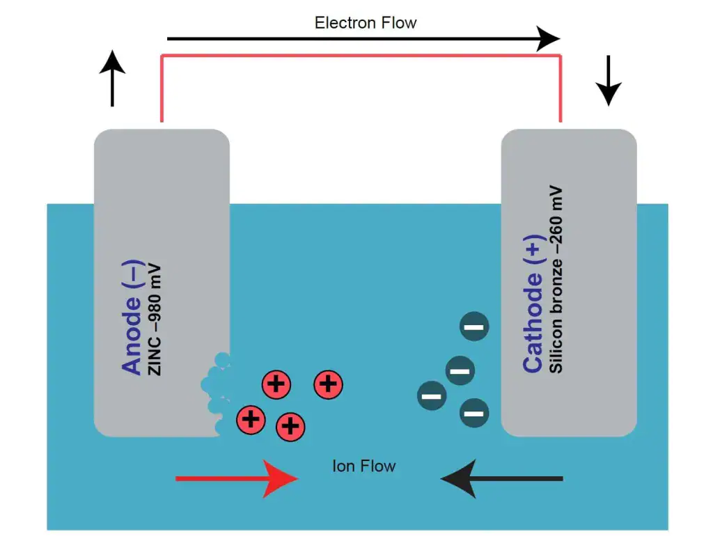
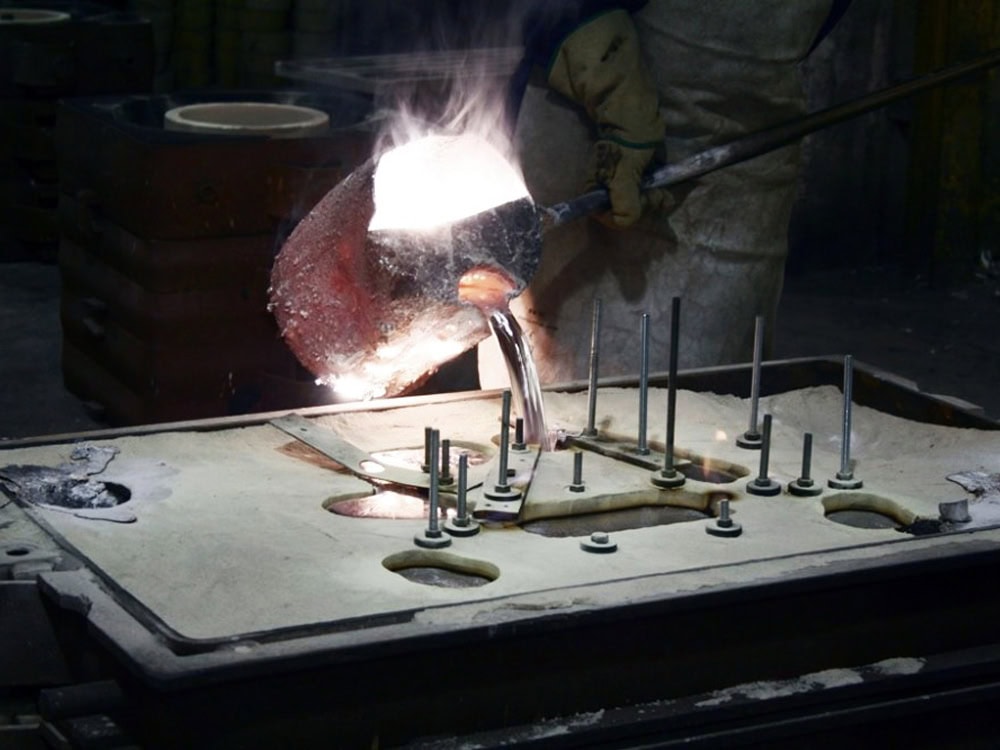
The core working principle of sacrificial anodes is based on the electrochemical galvanic cell reaction. Its electrode potential (-1.10V, relative to the copper/saturated copper sulfate electrode CSE) is significantly more negative than that of steel (-0.85V, CSE). When the zinc anode is electrically connected to the protected metal and placed in the same electrolyte environment, the zinc acts as the anode and preferentially loses electrons through oxidation (Zn-2e⁻=Zn²⁺). The electrons are transferred to the surface of the protected metal through the conductive medium, inhibiting its reduction reaction, thus achieving the corrosion protection effect of “sacrificing itself to protect the base metal.”
High-quality zinc sacrificial anodes are not made of pure zinc, but rather through the precise addition of alloying elements such as aluminum and cadmium. Strict control of impurities such as iron, copper, and lead optimizes their electrochemical performance and dissolution characteristics, preventing anode passivation or intergranular corrosion.
Alloying Elements and Their Functions
The performance of zinc sacrificial anodes depends on the precise proportioning of alloying elements and the strict control of impurity elements. Currently, mainstream zinc anodes use a zinc-aluminum-cadmium ternary alloy system. The relevant composition requirements are clearly specified in authoritative standards such as GB/T 4950-2021 “Zinc-Aluminum-Cadmium Alloy Sacrificial Anodes” and ASTM F1182-07 (2023) “Sacrificial Zinc Anodes“.
| Element | ASTM B418 Type I | ASTM B418 Type II | MIL-A-18001K | DNV-RP-B401 | GB/T 4950-2021 |
|---|---|---|---|---|---|
| Al | 0.1~0.5 | ≤0.005 | 0.1~0.5 | 0.1~0.5 | 0.1~0.7 |
| Cd | 0.025~0.07 | ≤0.003 | 0.025~0.07 | 0.025~0.07 | 0.025~0.07 |
| Fe | ≤0.005 | ≤0.005 | ≤0.005 | ≤0.005 | ≤0.005 |
| Pb | ≤0.006 | ≤0.003 | ≤0.006 | ≤0.006 | ≤0.006 |
| Cu | ≤0.006 | ≤0.003 | ≤0.006 | ≤0.006 | ≤0.006 |
| Si | ≤0.125 | ≤0.005 | ≤0.125 | ≤0.125 | — |
| Impurities | ≤0.1 | ≤0.2 | ≤0.1 | ≤0.1 | ≤0.3 |
| Zn | Balance | Balance | Balance | Balance | Balance |
← Swipe left/right to view full table →
The basic component of the zinc anode is zinc (balance, ≥99.3%). The core alloying elements are aluminum (Al) and cadmium (Cd). The content range of both (Al and Cd) is strictly limited, and their synergistic effect determines the core performance of the anode.
Aluminum (Al)
The content is controlled between 0.10% and 0.50%, and it is the “activation core element” of the zinc anode. Pure zinc easily forms a dense zinc oxide passivation film in an electrolyte environment, leading to a sharp drop in current efficiency and failure of cathodic protection. Aluminum preferentially reacts with oxygen to form loose aluminum oxide. This product easily detaches from the anode surface, preventing the formation of a dense passivation layer and ensuring stable output of protective current.
At the same time, aluminum refines the grain structure of the zinc alloy, improving the mechanical strength of the anode and preventing damage during transportation or installation. It should be noted that when the aluminum content is below 0.10%, the activation effect is insufficient, and the anode is prone to passivation; when it is above 0.50%, it will cause the anode potential to shift, reducing the potential difference with steel and affecting the protective driving force.
Cadmium (Cd)
The cadmium content is controlled between 0.025% and 0.07%. It is the “key element” for optimizing the corrosion morphology of zinc anodes. Cadmium-free pure zinc anodes are prone to intergranular corrosion during corrosion. The corrosive medium penetrates deep into the interior along the grain boundaries, causing large pieces of anode material that have not participated in the electrochemical reaction to detach. Moreover, the current efficiency can only reach below 60%.
Cadmium further refines the grain structure, changes the corrosion path of the anode, and promotes uniform layered dissolution of the anode. This significantly improves the utilization rate of the zinc anode, and the current efficiency in seawater can reach over 95%. In addition, cadmium improves the hydrogen embrittlement resistance of the zinc alloy, preventing structural embrittlement caused by hydrogen evolution at high current densities.
Strict Control of Impurities and Their Hazards
Zinc anodes have extremely stringent requirements for the content of impurity elements such as iron (Fe), copper (Cu), lead (Pb), and silicon (Si). These impurities are the “core hidden dangers” that lead to the degradation of anode performance. GB/T 4950-2021 clearly stipulates that: Fe ≤ 0.005%, Cu ≤ 0.005%, Pb ≤ 0.006%, Si ≤ 0.125%, and the total impurity content must be ≤ 0.15%.
- Iron (Fe) and Copper (Cu)
Both are electropositive impurities. When mixed into the zinc anode, they form micro-batteries internally, leading to self-corrosion of the zinc anode. When the Fe content exceeds 0.005%, the anode self-corrosion rate increases by more than 30%; excessive Cu content will exacerbate localized pitting corrosion on the anode surface, destroying its uniform dissolution characteristics.
- Lead (Pb)
Lead easily segregates at the grain boundaries of the zinc alloy, counteracting the effect of cadmium in refining grains and inhibiting intergranular corrosion, instead promoting intergranular corrosion and leading to premature anode failure. At the same time, the precipitation of lead causes environmental pollution and does not meet environmental protection requirements.
- Silicon (Si)
Excessive silicon content can lead to the formation of hard silicides. This reduces the plasticity and toughness of the zinc anode, making it prone to cracking in low-temperature environments or under external impact. Additionally, the silicides can adhere to the anode surface, affecting current conduction.
Electrochemical Performance
Electrochemical performance is a core indicator for evaluating whether a zinc sacrificial anode can meet corrosion protection requirements. Key indicators include open-circuit potential, closed-circuit potential, current efficiency, and actual capacity.
| Performance Parameter | ASTM B418 Type I | ASTM B418 Type II | MIL-A-18001K | DNV-RP-B401 | GB/T 4950-2021 |
|---|---|---|---|---|---|
| Open Circuit Potential | ≥-1.05V | ≥-1.10V | ≥-1.05V | ≥-1.05V | ≥-1.05V |
| Operating Potential | ≥-1.00V | ≥-1.05V | ≥-1.00V | ≥-1.00V | ≥-1.00V |
| Minimum Current Efficiency | 95% (Seawater, 3mA/cm²) |
95% (High-purity Application) |
95% (Seawater) | 95% (Seawater) | 95% (Seawater); 65% (Soil) |
| Typical Capacity | ≥780Ah/kg | ≥780Ah/kg | ≥770Ah/kg (355Ah/lb) |
≥780Ah/kg | ≥780Ah/kg (Seawater); ≥530Ah/kg (Soil) |
| Dissolution Performance | Uniform dissolution, easy detachment of products |
← Swipe left/right to view full table →
- Open Circuit Potential
Open circuit potential refers to the potential difference between the zinc anode and the reference electrode (copper/saturated copper sulfate electrode, CSE) under no-load conditions. Standard requirements: In seawater, the open circuit potential is -1.05V to -1.09V (CSE); in soil, ≤-1.05V (CSE); and in freshwater environments, -1.03V to -1.07V (CSE).
- Working Potential
Working potential refers to the potential of the zinc anode when it is outputting protective current. If the working potential is too negative, it can lead to hydrogen embrittlement of the protected steel (especially high-strength steel); if it is too positive, it cannot provide effective protection. Standard requirements: In seawater, the working potential is -1.05V to -1.08V (CSE); in soil, ≤-1.03V (CSE), and the fluctuation range must be ≤0.02V to ensure protection stability.
- Current Efficiency
Current efficiency refers to the effective protective current output from the oxidation reaction of the zinc anode. Higher current efficiency leads to a longer actual service life of the anode. Standard requirements: ≥95% in seawater (at a current density of 1 mA/cm²), ≥65% in soil (at a current density of 0.03 mA/cm²), and ≥80% in freshwater environments (at a current density of 0.5 mA/cm²).
- Actual Capacity
Actual capacity refers to the amount of electricity that a unit weight of zinc anode can actually output. Its unit is Ah/kg, and it directly determines the protective capacity of the anode. Standard requirements: actual capacity in seawater ≥ 780 Ah/kg, in soil ≥ 530 Ah/kg, and in freshwater environments ≥ 680 Ah/kg. This is significantly higher than the capacity of magnesium anodes in soil, which is key to the significant advantage of zinc anodes in low-resistivity environments.
- Consumption Rate
The consumption rate refers to the amount of zinc anode consumed per year when outputting 1 ampere of current. Its unit is kg/(A·Yr), and it is a core parameter for calculating the anode’s service life. Standard requirements: consumption rate ≤ 11.88 kg/(A·Yr) in seawater, ≤ 17.25 kg/(A·Yr) in soil, and ≤ 13.5 kg/(A·Yr) in freshwater environments.
Influence of the Medium
The electrochemical performance of zinc anodes varies with factors such as the resistivity, salinity, temperature, and flow rate of the electrolyte. This is also the core basis for differentiating zinc anodes used in seawater, freshwater, and soil.
- Seawater
High salinity (approximately 3.5%), low resistivity (<15 Ω·m), and strong ionic conductivity result in a stable open-circuit potential for the zinc anode, the highest current efficiency (≥95%), and uniform dissolution. This is the optimal application scenario for zinc anodes.
- Freshwater
Low salinity (<0.1%), moderate resistivity (15~100 Ω·m), and insufficient ion concentration result in slightly lower current efficiency of the anode compared to seawater, and easily lead to the formation of zinc hydroxide corrosion products. Therefore, the activity needs to be improved through fine-tuning with alloying elements.
- Soil
Soil resistivity fluctuates significantly (depending on humidity and soil type, with the optimal being < 15 Ω·m). Electrolyte distribution is uneven, and there is also microbial corrosion and stray current interference. Consequently, the zinc anode has the lowest current efficiency (≥65%) and the highest consumption rate. It usually requires backfill materials such as gypsum and sodium sulfate to reduce contact resistance and maintain anode activity.
Specification Classification
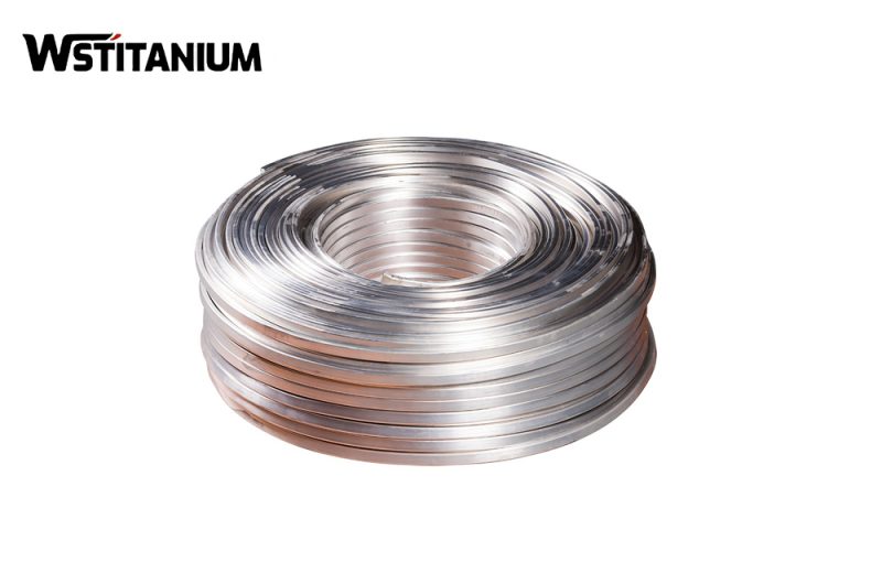
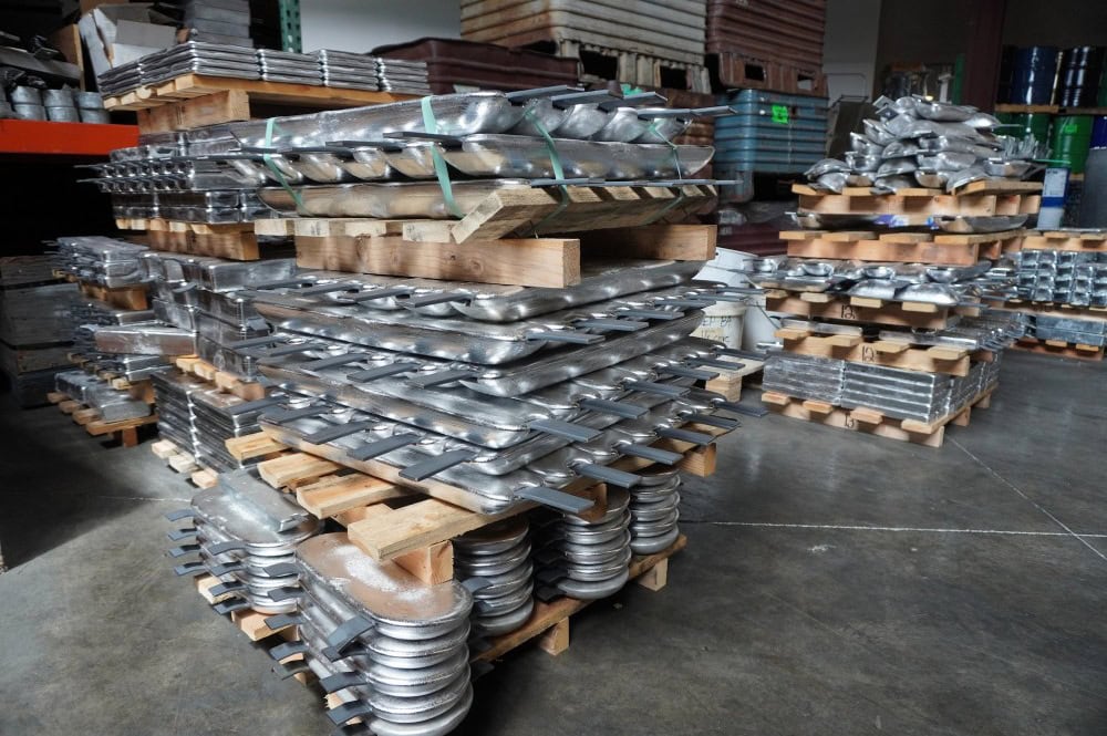
Zinc sacrificial anodes are categorized by installation and application. Based on installation, they can be divided into welded zinc anodes and bolted zinc anodes; based on application, they can be divided into seawater zinc anodes, freshwater zinc anodes, soil zinc anodes, and ship hull zinc anodes. Different specifications of anodes are specifically optimized in terms of size, weight, and structural design. All specifications must comply with the dimensional tolerances and performance requirements of GB/T 4950-2021 and ASTM F1182-07 (2023).
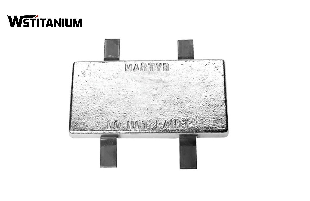
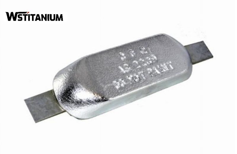
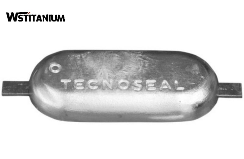
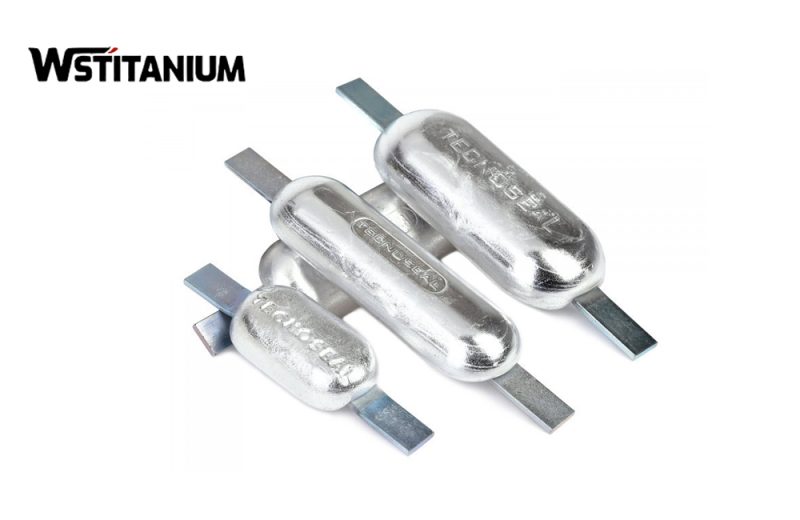
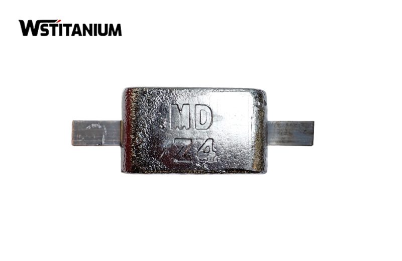
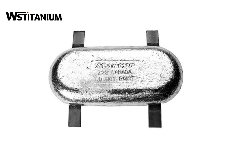
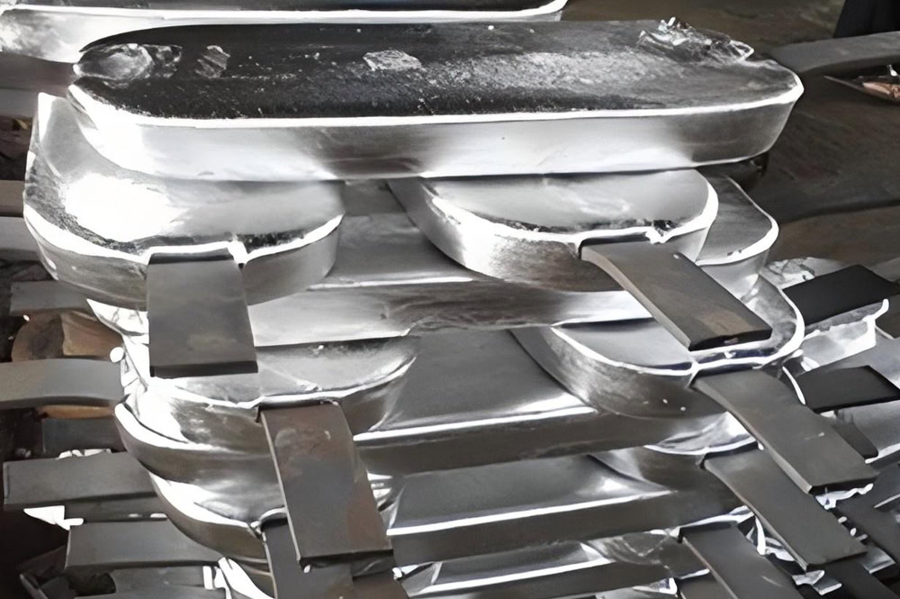
Welded zinc anodes are the most commonly used anodes. Their core feature is the integration of steel weld legs or steel strips during the anode body casting. During installation, the weld legs are welded and fixed to the protected metal (such as ship hulls, steel piles, and storage tanks). They have good conductivity and a strong connection. Applications include ship hull bottoms, storage tank inner walls, and offshore platform steel piles.

The anode body is block-shaped, plate-shaped, or strip-shaped. The weld feet are made of Q235 carbon steel with a galvanized surface for corrosion protection (to prevent the weld feet from corroding before the anode). The weld leg and anode body are integrally cast, with no weld seams, preventing excessive contact resistance at the connection point.
Welded Zinc Anodes for Storage Tanks (ZC Series)
- ZC-1 Type: 750×(115+135)×130mm, weld leg length 900mm, diameter 16mm, net weight 82kg, gross weight 85kg;
- ZC-2 Type: 500×(115+135)×130mm, weld leg length 650mm, net weight 55kg;
- ZC-3 Type: 500×(105+135)×100mm, net weight 39kg;
- ZC-4 Type: 300×(105+135)×100mm, weld leg diameter 12mm, net weight 24.6kg.
Welded Zinc Anodes for Marine Steel Piles (ZT Series)
- ZT-1 Type: 1000×(115+135)×130mm, flat steel weld leg size 16×8mm, net weight 105kg;
- ZT-2 Type: 800×(100+120)×120mm, net weight 78kg, suitable for corrosion protection of intertidal steel piles.
DC arc welding is required. The welding area between the weld leg and the protected metal should be ≥50cm² to ensure good conductivity. After welding, slag must be cleaned, and anti-corrosion coating should be applied to the weld to prevent isolated corrosion. The anode spacing should be ≥3 times the anode length to avoid interference between adjacent anode currents.
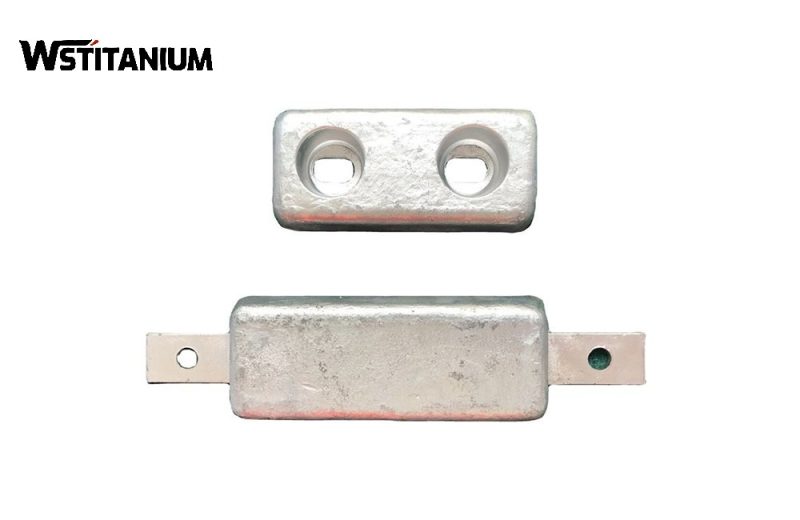
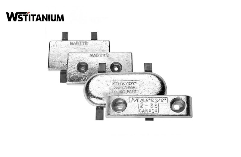
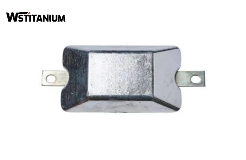
The core feature of bolted zinc anodes is the pre-drilled bolt holes in the anode body, or the integrated bolt-type steel core. During installation, bolts and nuts secure the anode to the protected metal without welding, making it suitable for applications requiring periodic replacement, such as ship ballast tanks, freshwater pipeline flanges, and removable equipment housings.
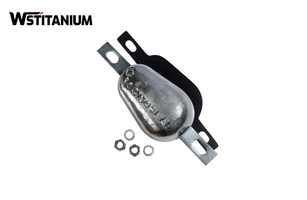
The anode body can be plate-shaped, block-shaped, or disc-shaped. One to two bolt holes are pre-drilled in the center or at the edge. Bolts are made of stainless steel (304 or 316) to prevent corrosion from affecting disassembly. A conductive gasket (copper or graphite) must be installed between the anode and the protected metal to eliminate contact resistance and ensure smooth current conduction.
Disc-shaped bolted zinc anodes
- Diameter 200~500mm, thickness 30~80mm, center bolt hole diameter 16~24mm, net weight 5~30kg, suitable for condensers, heat exchangers, etc.
Block-shaped bolted zinc anodes
- 300×200×50mm, 400×300×60mm, double bolt hole design on the edge, net weight 8~25kg, suitable for pipe supports, small steel structures.
- 500×300×70mm, bolt hole diameter 20mm, stainless steel bolt length 100mm, net weight 32kg, water pressure resistant, impact resistant.
During installation, the bolts must be tightened to ensure a tight fit between the anode and the protected metal; the conductive gasket must be intact and undamaged, and insulating gaskets must not be used as substitutes.
Seawater Zinc Anodes
Seawater zinc anodes are specialized anodes designed for high-salt media such as seawater and salt spray. They are a core application category of zinc anodes, suitable for ships, offshore platforms, drilling platforms, harbor steel piles, seawater condensers, etc. Their alloy composition and structural design are optimized for uniform dissolution in high-ion-concentration environments, preventing localized pitting corrosion.
Performance Optimization
The aluminum content in the alloy is controlled at 0.3%~0.5%, and the cadmium content at 0.04%~0.07%, ensuring no passivation in high-flow-rate, high-salinity seawater. Current efficiency ≥95%, open-circuit potential stable at -1.05V~-1.09V (CSE), actual capacitance ≥780Ah/kg, consumption rate ≤11.88kg/(A・Yr).
Structure
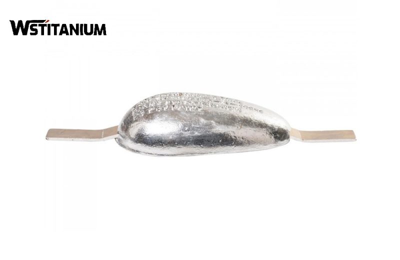
Mostly block, plate, or strip-shaped. Some are irregularly shaped (e.g., teardrop-shaped, segmented) to adapt to different marine structures.
- Seawater zinc anodes for offshore platforms: 1200×(120+140)×150mm, weld leg length 1000mm, net weight 150kg, resistant to seawater flow velocity ≤5m/s, and wave impact resistant;
- Seawater zinc anodes for harbor steel piles: 1000×100×100mm, strip-shaped welded type, single piece net weight 60kg, spaced 2~3m apart;
- Teardrop-shaped seawater zinc anodes: length 500~800mm, maximum diameter 150mm, integrated weld leg, net weight 15~35kg, suitable for irregularly shaped structures such as ship propellers and rudder blades.
During installation, keep away from the antifouling paint area on the hull to avoid anode passivation caused by toxic substances in the antifouling paint; in high-velocity sea areas (such as straits and estuaries), the number of anodes needs to be increased to compensate for current loss caused by excessive flow velocity; regularly clean the anode surface of marine organisms (such as barnacles and shellfish) to prevent biological adhesion and anode coverage.
Freshwater Zinc Anode
Freshwater zinc anodes are suitable for low-salt, low-conductivity media such as rivers, lakes, reservoirs, and drinking water pipelines. Due to the low ion concentration and high resistivity of freshwater, the zinc anode requires optimized alloy ratios to improve activation and prevent passivation. It is suitable for applications such as freshwater pipelines, hydraulic gates, hydropower station steel structures, and freshwater storage tanks.
Performance Optimization
The aluminum content is slightly higher than that of seawater anodes, controlled at 0.4%~0.5%, to enhance activation. Cadmium content is 0.03%~0.06%, current efficiency ≥80%, open circuit potential -1.03V~-1.07V (CSE), actual capacity ≥680Ah/kg, consumption rate ≤13.5kg/(A・Yr); some freshwater anodes may have trace amounts of tin (Sn≤0.02%) added to improve dissolution uniformity in soft water.
Structure
Mostly rod-shaped or block-shaped, facilitating installation on the inner wall of pipes or in gate grooves.
- **Freshwater Pipeline Rod-Shaped Zinc Anodes:** Diameter 30-60mm, Length 500-1000mm, threaded or welded ends, net weight 3-12kg, suitable for DN100-DN1000 pipes;
- **Hydraulic Gate Block-Shaped Freshwater Zinc Anodes:** 600×400×80mm, bolt-fixed type, net weight 45kg, resistant to freshwater immersion and resistant to silt abrasion;
- **Drinking Water Storage Tank Freshwater Zinc Anodes:** 400×300×50mm, lead-free and mercury-free environmentally friendly formula, meets drinking water hygiene standards, net weight 28kg.
In soft water (hardness < 50 mg/L), a small amount of packing material (gypsum powder) is required to increase the local ion concentration. The installation location must avoid dead corners in the pipeline to ensure water circulation and prevent stagnant water areas around the anode from causing passivation. Anodes used in drinking water systems must pass hygiene and safety testing to prevent the precipitation of harmful impurities.
Soil Zinc Anodes
Soil zinc anodes are suitable for underground metal structures such as buried pipelines, underground storage tanks, subway tunnel steel structures, and bridge pile foundations. Due to the large fluctuations in soil resistivity and uneven dielectric distribution, the anodes are often pre-packaged and used with filler material to reduce contact resistance. They are only suitable for low resistivity environments with soil resistivity < 15 Ω·m. For high resistivity soils, magnesium anodes should be used instead.
Performance Optimization
Alloy elements are strictly controlled for impurity content (Fe ≤ 0.003%, Cu ≤ 0.003%) to avoid self-corrosion caused by microorganisms in the soil. Current efficiency ≥ 65%, open circuit potential ≤ -1.05V (CSE), actual capacitance ≥ 530 Ah/kg, and consumption rate ≤ 17.25 kg/(A·Yr).
Structure
Primarily pre-packaged rod-shaped or block-shaped anodes. The pre-packaged anode includes the anode body, filler material, conductive cable, and moisture-proof sealing bag. Common specifications (ZP series).
- ZP-1 Type Soil Zinc Anode: 1000×(78+88)×85mm, steel leg length 700mm, net weight 49kg, filler material 50kg (gypsum:sodium sulfate = 7:3), cable length 3m;
- ZP-2 Type Soil Zinc Anode: 1000×(65+75)×65mm, net weight 32kg, filler material 45kg, suitable for water supply and drainage pipelines;
- ZP-3 Type Soil Zinc Anode: 800×(60+80)×65mm, net weight 24.5kg, suitable for small buried steel structures;
- ZP-8 Type Soil Zinc Anode: 600×(40+48)×45mm, net weight 8.7kg, suitable for shallow buried pipelines.
Burial depth ≥1m, vertical distance from buried pipeline 0.5~1.5m, avoid parallel arrangement with pipeline; the filler material must evenly wrap the anode, and damage or exposure is prohibited; after welding the cable to the pipeline, anti-corrosion treatment is required to prevent cable joint corrosion.
Zinc Anodes for Ship Hulls
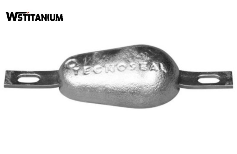
Zinc anodes for ship hulls are specialized anodes designed specifically for ships, suitable for hull shells, ballast tanks, seawater cooling systems, rudder systems, propellers, and other components. They must simultaneously meet multiple requirements, including resistance to seawater corrosion, wave impact resistance, compatibility with antifouling paints, and no risk of hydrogen embrittlement, making them a core material for ship corrosion protection.
- Zinc anodes for ship hulls: Plate-shaped welded type, dimensions 700×300×80mm, 900×400×100mm, weld legs are flat steel, net weight 35~80kg, evenly arranged along the outer hull plating, spacing 1.5~2m;
- Zinc anodes for ballast tanks: Bolted type, 500×300×70mm, stainless steel bolts, net weight 32kg, resistant to water pressure and cargo impact;
The hull anodes must be installed below the waterline to avoid passivation caused by exposure to the water surface; when connected to the aluminum hull structure, insulating gaskets must be installed to prevent galvanic corrosion between zinc and aluminum; the remaining amount of anodes should be checked regularly, and when the anodes are consumed to 1/3 of their original weight, they must be replaced in time to avoid hull corrosion.
Zinc Sacrificial Anode Standards
The manufacturing, quality inspection, and application of zinc sacrificial anodes must adhere to authoritative standards. International standards are primarily based on the American Society for Testing and Materials (ASTM). Some applications also require compliance with petroleum industry standards (SY).
ASTM F1182-07 (2023)
《Standard Specification for Anodes, Sacrificial Zinc Alloy》: The internationally recognized standard for zinc sacrificial anodes. Published by ASTM, and last revised in 2023, it classifies zinc anodes into Category 1 (cored anodes, such as weld legs and bolt cores) and Category 2 (coreless anodes, such as rods and plates). It further subdivides the types and specifications of specialized anodes for applications such as ship hulls, submarines, and heat exchangers.
DNV-RP-B401-2021
This is an authoritative guide for the design of ship cathodic protection systems, detailing the arrangement density, current demand calculation, and installation spacing of rudder anodes. It requires that the total current output of the rudder anodes must meet the protective current density of the rudder’s steel base (≥10mA/m² in seawater).
Mil-A-18001k (US Military Standard)
“Zinc Alloy Sacrificial Anodes,” is developed for military and special vessels. The impurity content control is stricter than ASTM B418 (iron ≤0.001%), and it requires that the anode does not crack under vibration and impact conditions, adapting to the harsh operating environment of military ship rudders.
“Cathodic protection of steel in seawater and in saline or brackish water,” is an international standard for cathodic protection of steel in seawater and saline water. It supplements the requirements for zinc anode placement density, lifespan calculation, and system compatibility in marine environments.
Common Zinc Sacrificial Anode Specifications
Ship Anode (Single Core)
| Model | Standard Size/mm (A×B×C) |
Core Size/mm | Net Weight /kg | Gross Weight /kg | |||
|---|---|---|---|---|---|---|---|
| D | E | F | G | ||||
| TC-ZN-H-1 | 800×140×60 | 900 | 45 | 6 | 10 | 38.2 | 40 |
| TC-ZN-H-2 | 800×140×50 | 900 | 45 | 6 | 8 | 32.7 | 34.5 |
| TC-ZN-H-3 | 800×140×40 | 900 | 45 | 6 | 6 | 26.7 | 28.5 |
| TC-ZN-H-4 | 600×120×50 | 700 | 40 | 6 | 8 | 20.4 | 21.6 |
| TC-ZN-H-5 | 400×120×50 | 470 | 35 | 5 | 8 | 13.5 | 14.1 |
| TC-ZN-H-6 | 500×100×40 | 580 | 40 | 5 | 6 | 11.4 | 12.2 |
| TC-ZN-H-7 | 400×100×40 | 460 | 30 | 5 | 6 | 9.1 | 9.6 |
| TC-ZN-H-8 | 300×100×40 | 360 | 30 | 4 | 6 | 6.8 | 7.1 |
| TC-ZN-H-9 | 250×100×40 | 310 | 30 | 4 | 6 | 5.6 | 5.8 |
| TC-ZN-H-10 | 180×70×40 | 230 | 25 | 4 | 6 | 2.5 | 2.7 |
← Swipe left/right to view full table →
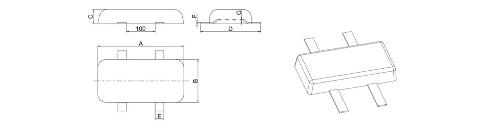
Ship Anode (Double Core)
| Model | Standard Size/mm (A×B×C) |
Core Size/mm | Net Weight /kg | Gross Weight /kg | |||
|---|---|---|---|---|---|---|---|
| D | E | F | G | ||||
| TC-ZN-H-11 | 300×150×50 | 360 | 30 | 4 | 6 | 14.8 | 15.4 |
| TC-ZN-H-12 | 300×150×40 | 360 | 30 | 4 | 6 | 11.8 | 12.4 |
← Swipe left/right to view full table →
Ship Anode (Bolted Type)
| Model | Standard Size/mm (A×B×C) |
Core Size/mm | Net Weight /kg | Gross Weight /kg | |||
|---|---|---|---|---|---|---|---|
| D | E | F | G | ||||
| TC-ZN-H-13 | 300×150×50 | 250 | 50 | 3 | 10 | 14.8 | 15 |
| TC-ZN-H-14 | 300×150×40 | 250 | 50 | 3 | 10 | 11.8 | 12 |
← Swipe left/right to view full table →
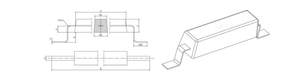
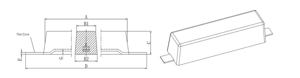
Ballast Water Tanks Anode
| Model | Standard Size/mm A×(B1+B2)×C |
Core Size/mm | Net Weight /kg | Gross Weight /kg | |||||
|---|---|---|---|---|---|---|---|---|---|
| D | E | F | G | H | |||||
| TC-ZN-T-1 | 500×(115+135)×130 | 800 | 50 | 6 | 40 | 60 | 56.9 | 59.3 | |
| TC-ZN-T-2 | 1500×(65+75)×70 | 1800 | — | φ16 | 20 | 40 | 50 | 53.1 | |
| TC-ZN-T-3 | 500×(110+130)×120 | 800 | 50 | 6 | 40 | 60 | 50 | 52.4 | |
| TC-ZN-T-4 | 1000×(58.5+78.5)×68 | 1300 | — | φ16 | 20 | 40 | 31.6 | 34 | |
| TC-ZN-T-5 | 800×(56+74)×65 | 1100 | — | φ16 | 20 | 40 | 23 | 25 | |
| TC-ZN-T-6 | 1150×(48+54)×51 | 1450 | — | φ12 | 15 | 35 | 20.5 | 21.9 | |
| TC-ZN-T-7 | 250×(80+100)×85 | 310 | 30 | 4 | 8 | 0 | 13.4 | 13.7 | |
| TC-ZN-T-8 | 200×(70+90)×70 | 260 | 30 | 3 | 8 | 0 | 7.8 | 8 | |
← Swipe left/right to view full table →
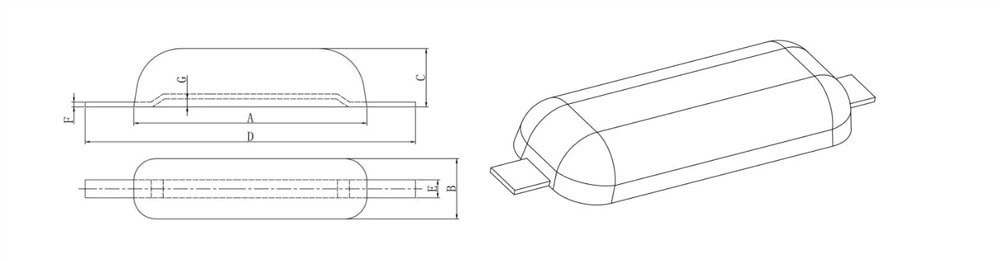
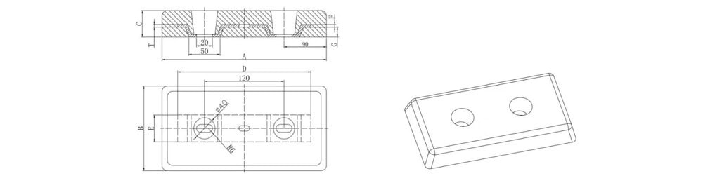
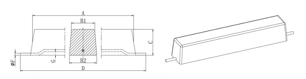
Marine Structure Anode
| Model | Standard Size/mm A×(B1+B2)×C |
Threaded Core Size /mm | Flat Core Size/mm | Net Weight /kg | Gross Weight /kg | |||||
|---|---|---|---|---|---|---|---|---|---|---|
| D | F | G | D | E | F | G | ||||
| TC-ZN-I-1 | 1000×(115+135)×130 | 1250 | 18 | 45 | 1250 | 40 | 8 | 45 | 114.1 | 116.5 |
| TC-ZN-I-2 | 750×(115+135)×130 | 1000 | 16 | 45 | 1000 | 40 | 6 | 45 | 86 | 87.5 |
| TC-ZN-I-3 | 500×(115+135)×130 | 750 | 16 | 45 | 750 | 40 | 8 | 45 | 56.9 | 58 |
| TC-ZN-I-4 | 500×(105+135)×100 | 750 | 16 | 35 | 750 | 40 | 6 | 35 | 41.9 | 43 |
← Swipe left/right to view full table →
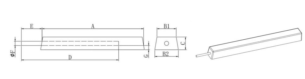
Cooling System Anode (Strip Type)
| Model | Standard Size/mm A×(B1+B2)×C |
Core Size/mm | Net Weight /kg | Gross Weight /kg | |||
|---|---|---|---|---|---|---|---|
| D | E | F | G | ||||
| TC-ZN-E-1 | 500×(115+135)×130 | 620 | 50 | 6 | 10 | 56.9 | 58.3 |
| TC-ZN-E-2 | 1000×(80+100)×80 | 1200 | 30 | 6 | 8 | 50 | 51.7 |
| TC-ZN-E-3 | 500×(105+135)×100 | 620 | 40 | 6 | 10 | 42 | 43.2 |
| TC-ZN-E-4 | 500×(80+100)×80 | 620 | 30 | 6 | 8 | 24.8 | 25.6 |
| TC-ZN-E-5 | 400×(110+120)×50 | 500 | 35 | 4 | 6 | 15.8 | 16.3 |
| TC-ZN-E-6 | 300×(140+160)×40 | 360 | 60 | 4 | 6 | 12.3 | 13 |
| TC-ZN-E-7 | 200×(90+110)×40 | 250 | 30 | 3 | 6 | 5.5 | 5.7 |
← Swipe left/right to view full table →
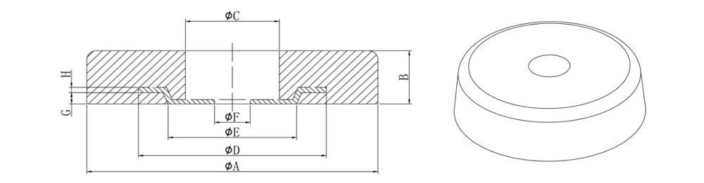
Cooling System Anode (Disc Type)
| Model | Standard Size/mm | Core Size/mm | Net Weight /kg | Gross Weight /kg | ||||||
|---|---|---|---|---|---|---|---|---|---|---|
| A×B | C | D | E | F | H | G | ||||
| TC-ZN-E-8 | 300×60 | 40 | 80 | 50 | 12 | 6 | 6 | 28.4 | 28.6 | |
| TC-ZN-E-9 | 360×40 | 50 | 100 | 70 | 14 | 5 | 6 | 27.3 | 27.6 | |
| TC-ZN-E-10 | 300×40 | 40 | 80 | 50 | 12 | 5 | 6 | 18.8 | 19 | |
| TC-ZN-E-11 | 200×50 | 35 | 75 | 45 | 10 | 5 | 4 | 10 | 10.2 | |
| TC-ZN-E-12 | 180×50 | 35 | 75 | 45 | 10 | 5 | 4 | 8 | 8.1 | |
| TC-ZN-E-13 | 120×100 | 30 | 75 | 45 | 10 | 8 | 4 | 6.5 | 6.7 | |
← Swipe left/right to view full table →
Tank Internal Anode
| Model | Standard Size/mm A×(B1+B2)×C |
Core Size/mm | Net Weight /kg | Gross Weight /kg | ||
|---|---|---|---|---|---|---|
| D | F | G | ||||
| TC-ZN-C-1 | 750×(115+135)×130 | 900 | 16 | 10 | 85.6 | 86.9 |
| TC-ZN-C-2 | 500×(115+135)×130 | 650 | 16 | 10 | 57 | 58 |
| TC-ZN-C-3 | 500×(105+135)×100 | 650 | 16 | 10 | 41.9 | 42.9 |
| TC-ZN-C-4 | 300×(105+135)×100 | 400 | 12 | 10 | 25.3 | 25.6 |
← Swipe left/right to view full table →
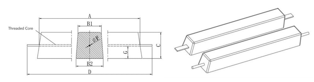
Buried Pipeline Anode
| Model | Standard Size/mm A×(B1+B2)×C |
Core Size/mm | Net Weight /kg | Gross Weight /kg | |||
|---|---|---|---|---|---|---|---|
| D | E | F | G | ||||
| TC-ZN-P-1 | 1000×(78+88)×85 | 700 | 100 | 16 | 30 | 49.4 | 50.4 |
| TC-ZN-P-2 | 1000×(65+75)×65 | 700 | 100 | 16 | 25 | 31.5 | 32.5 |
| TC-ZN-P-3 | 800×(60+80)×65 | 600 | 100 | 12 | 25 | 25.5 | 26 |
| TC-ZN-P-4 | 800×(55+64)×60 | 500 | 100 | 12 | 20 | 20 | 20.4 |
| TC-ZN-P-5 | 650×(58+64)×60 | 400 | 100 | 12 | 20 | 16.6 | 16.9 |
| TC-ZN-P-6 | 550×(58+64)×60 | 400 | 100 | 12 | 20 | 14 | 14.3 |
| TC-ZN-P-7 | 600×(52+56)×54 | 460 | 100 | 12 | 15 | 12.1 | 12.5 |
| TC-ZN-P-8 | 600×(40+48)×45 | 360 | 100 | 12 | 15 | 8.2 | 8.5 |
← Swipe left/right to view full table →
Conclusion
Zinc sacrificial anodes, as the core material of cathodic protection technology, play an irreplaceable role in corrosion protection in marine engineering, shipbuilding, buried pipelines, and water conservancy facilities due to their advantages of stable electronegativity, high current efficiency, convenient installation, and wide applicability. The guarantee of their core performance depends on the precise ratio of zinc-aluminum-cadmium alloy and the strict control of impurities such as iron, copper, and lead. Key electrochemical indicators such as open-circuit potential, operating potential, and current efficiency are crucial for differentiating compatibility with various media.

