
Zinc sacrificial anodes, with their unique technological advantages, have become the preferred solution for cathodic protection of small and medium-sized storage tanks and tanks in complex environments. They require no external power source, are extremely low-cost, and are suitable for tanks in remote areas without power supply. Their uniform current distribution, stable operating potential, and minimal stray current interference to surrounding metal structures make them suitable for densely packed tank farms. This article describes the applicable boundaries, technical specifications, and best practices of zinc sacrificial anodes in tank corrosion protection, providing comprehensive, authoritative, and practical technical guidance for the oil and gas, water, and chemical industries.
The Nature of Tank Corrosion
Outer Side of Tank Bottom (Buried Side)
The tank bottom plate is in direct contact with asphalt and soil. This is typical buried corrosion. This area is constantly in a moist, anaerobic state, experiencing oxygen concentration gradient corrosion, sulfate-reducing bacteria (SRB) microbial corrosion, chloride/sulfate ion corrosion, and crevice corrosion. The natural corrosion rate can reach 0.5-1.0 mm/a. Over 90% of tank leaks originate from bottom plate corrosion perforation.
Inner Side of Tank Bottom (Medium Side)
A 10-50 cm layer of free water is commonly present at the bottom of tanks storing crude oil, refined oil, and chemical raw materials. This water layer is enriched with corrosive components such as chloride ions, H₂S, and CO₂ from the medium, and also fosters the growth of large amounts of SRB microorganisms. The corrosion rate is more than 10 times that of the upper organic medium phase, with localized corrosion rates reaching 2.0 mm/a.
Inner tank wall
Divided into three corrosion zones: gas phase, oil-water interface, and liquid phase. The oil-water interface zone experiences intense localized corrosion due to oxygen concentration gradients and medium inhomogeneity. The corrosion rate in this zone is 3-5 times that of the liquid phase. The gas phase zone also presents a high risk of corrosion due to condensation corrosion caused by medium volatilization and condensation.
Outer tank wall and top
Primarily subject to atmospheric corrosion; coastal tanks are also susceptible to salt spray corrosion. The corrosion rate is relatively low, and coating protection is generally sufficient. Cathodic protection is only required in high-salt-spray and high-humidity environments.
The Electrochemical Nature of Corrosion
The corrosion of steel storage tanks in an electrolyte environment is a typical electrochemical galvanic cell process. Iron atoms lose electrons and dissolve due to oxidation in the anodic region. Electrons are transferred through the steel substrate to the cathodic region, where they are consumed by the depolarizing agents (oxygen, hydrogen ions, etc.), forming a complete current loop, leading to continuous corrosion and loss of the steel substrate.
- Anodic reaction (corrosion dissolution): Fe → Fe²⁺ + 2e⁻
- Cathode reaction (acidic/anaerobic environment): 2H⁺ + 2e⁻ → H₂
- Cathode reaction (neutral/weakly alkaline environment): O₂ + 2H₂O + 4e⁻ → 4OH⁻
The corrosion reaction originates from the potential difference between different areas of the steel substrate surface. The area with a more negative potential becomes the anodic region where dissolution occurs. The area with a more positive potential becomes the cathodic region where reduction occurs. The core principle of cathodic protection is to provide sufficient cathodic current to the protected steel substrate through external means, shifting the overall potential of the steel substrate negatively below the equilibrium potential of the anodic dissolution reaction, completely inhibiting the oxidation and dissolution of iron atoms, and achieving comprehensive corrosion protection of the steel substrate.
Advantages of Zinc Sacrificial Anodes
Extremely High Potential Matching
The operating potential of the zinc anode is stable at -1.00~-1.10V (vs CSE), perfectly matching the protection potential range of steel storage tanks (-0.85~-1.10V vs CSE).
Uniform Current Distribution
The output current of the zinc anode is stable, achieving uniform current coverage across the entire tank bottom and wall.
High Reliability
No external power supply or complex electrical commissioning requirements are needed. After installation, frequent maintenance is unnecessary, making it suitable for remote areas and storage tank scenarios without power supply.
Minimally Low Stray Current Interference
The output current of the zinc anode is stable, achieving uniform current coverage across the entire tank bottom and wall.
High Safety
The Type II zinc anode, compliant with ANSI/NSF 61 drinking water contact standards, will not cause secondary pollution to drinking water or food-grade media.
Excellent Cost-Effectiveness
For small to medium-sized storage tanks with a volume ≤5000m³, the initial investment of a zinc sacrificial anode system is only 30%~50% of that of an impressed current system.
Disadvantages of Zinc Sacrificial Anodes
Low Driving Voltage: The driving voltage of the zinc anode is only 0.2~0.3V. In dry soil or high-purity water environments with resistivity >2000Ω・cm, the output current drops sharply. This cannot meet protection requirements, necessitating replacement with a magnesium anode or an impressed current system.
Low Temperature Upper Limit: When the medium temperature exceeds 50℃, a dense zinc oxide passivation film forms on the zinc anode surface. This causes a positive potential shift, even exceeding the potential of steel, thus accelerating the corrosion of the steel storage tank.
Narrow pH Applicability Range: The stable operating pH range of the zinc anode is 6~11. In acidic environments with pH <6, the dissolution rate is too fast, significantly shortening its lifespan. Passivation easily occurs in strongly alkaline environments with pH > 11, resulting in loss of protective capability.
Insufficient compatibility with large storage tanks: For ultra-large crude oil storage tanks of 100,000 m³ and above, the required number of zinc anodes is excessive, significantly increasing installation and maintenance costs. Economic efficiency is lower than that of impressed current systems.
Types of Zinc Sacrificial Anodes for Storage Tanks
The core authoritative standard for zinc sacrificial anodes used in storage tanks is ASTM B418-21, “Standard Specification for Cast and Forged Zinc Anodes for Cathodic Protection.” This standard clearly defines the alloying elements, performance requirements, test methods, and acceptance rules for zinc anodes. It is the core basis for engineering design, procurement, and acceptance. ASTM B418-21 classifies zinc anodes into three types, each suitable for different application scenarios in storage tanks.
Elements: Zinc content ≥99.99%, with strict control over impurity content, including lead ≤0.003%, iron ≤0.0014%, copper ≤0.002%, and cadmium ≤0.003%. 0.05%~0.15% cadmium can be added as an activation element.
Core Performance: Current efficiency ≥90% in seawater environments; current efficiency ≥85% in soil environments; actual capacitance ≥740Ah/kg; open circuit potential -1.05~-1.15V (vs CSE).
Elements: Zinc content ≥99.9%, impurity control slightly more lenient than Type I, including lead ≤0.006%, iron ≤0.003%, copper ≤0.005%, and cadmium ≤0.006%.
Current efficiency in freshwater environments ≥85%, actual capacity ≥700Ah/kg, conforming to ANSI/NSF 61 drinking water contact standards, with no leaching of toxic or harmful substances.
Suitable tank scenarios: Municipal drinking water storage tanks, fire-fighting water tanks, reclaimed water storage tanks, and freshwater environment storage tanks. It is a dedicated anode type for water industry storage tanks.
Elements: High-purity zinc matrix, with 0.10%~0.30% aluminum and 0.02%~0.05% cadmium added as activation elements; impurity content control is consistent with Type I.
Core Performance: Current efficiency ≥80% in high resistivity environments. Better passivation resistance than Type I/II, suitable for medium to high resistivity environments of 1000~5000 Ω・cm.
Suitable Storage Tanks: Tank bottoms with dry sand and gravel foundations, underground storage tanks in high resistivity soil environments, and low-chloride freshwater storage tanks.
Besides ASTM B418-21, other internationally accepted standards include ISO 15589-1:2018 “Oil and gas industry – Cathodic protection of pipeline transportation systems – Part 1: Onshore pipelines”, ISO 19721:2017 “Oil and gas industry – Cathodic protection of the bottom of aboveground storage tanks”, and API RP 651-2021 “Catholic protection of aboveground storage tanks”. The Chinese standard is GB/T 4950-2002 “Zinc-aluminum-cadmium alloy sacrificial anodes“.
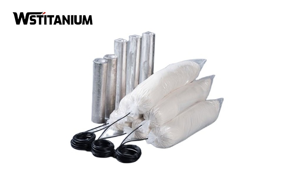
Structure: The core is a cast zinc anode body, externally wrapped with a standard-formula chemical packing compound. It is sealed in a high-strength cotton/non-woven bag. Copper core cables are welded to both ends of the anode. The weld joints are double-sealed with epoxy resin and heat-shrink tubing to prevent water infiltration and corrosion.
Packing Compound: 75% gypsum dihydrate, 20% bentonite, 5% anhydrous sodium sulfate, suitable for soil environments with resistivity of 500~2000 Ω·cm, the standard formulation for tank bottom applications.
High Resistivity Special Packing Compound: 50% gypsum dihydrate, 35% bentonite, 15% anhydrous sodium sulfate, suitable for dry soil environments with resistivity of 2000~5000 Ω·cm.
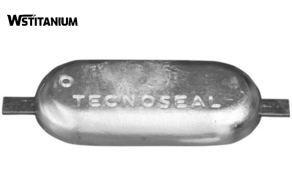
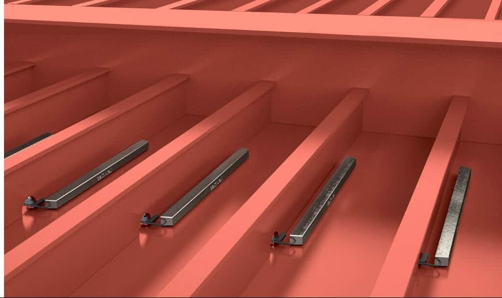
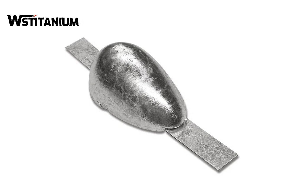
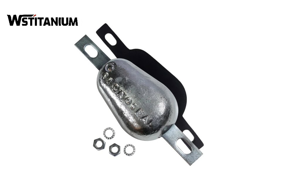
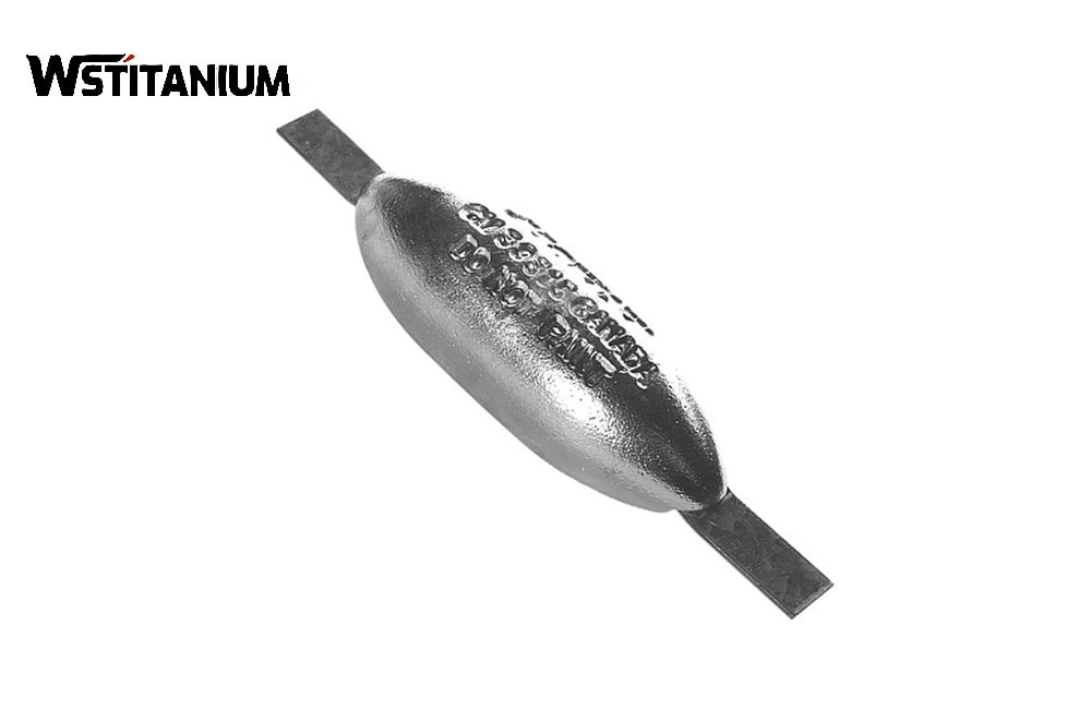
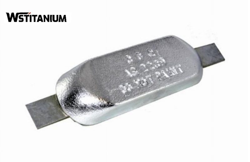
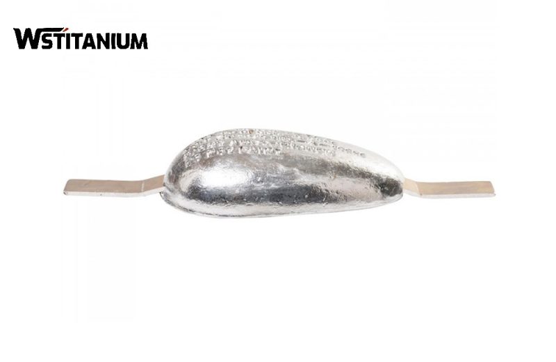
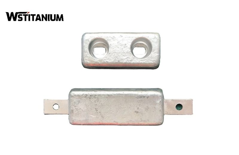
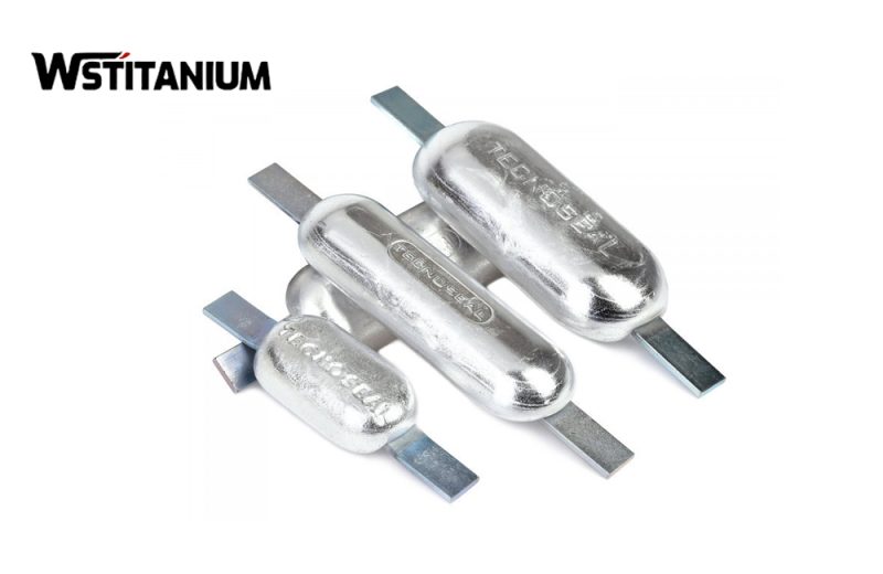
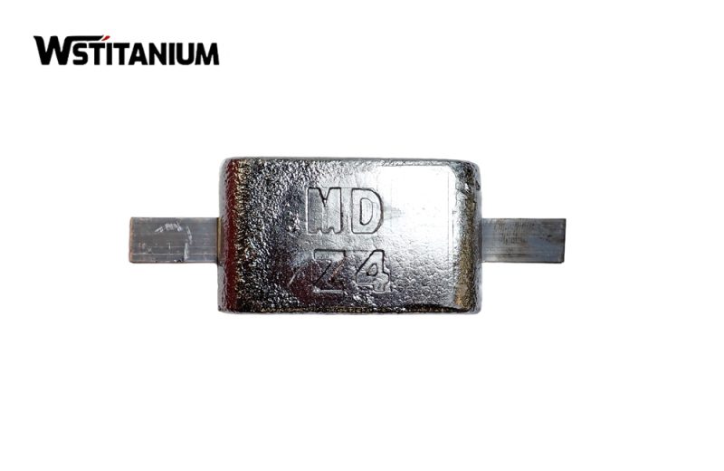
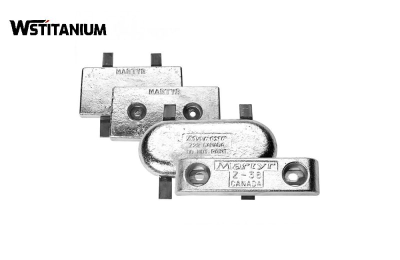
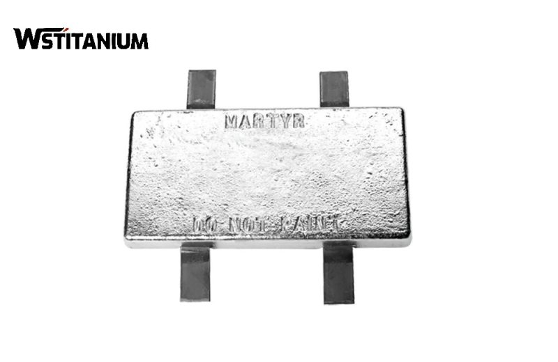
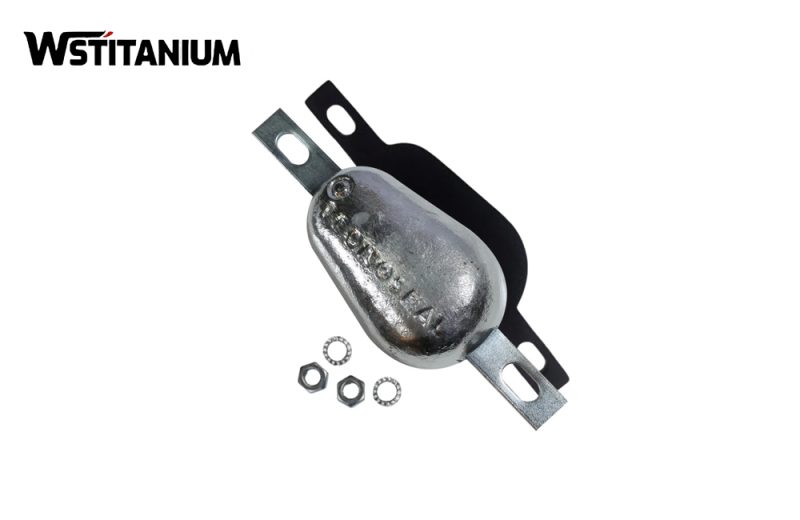
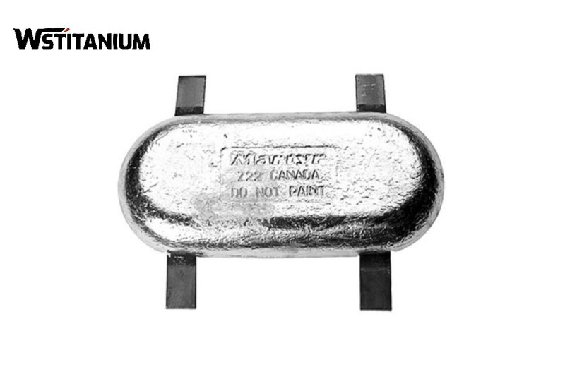
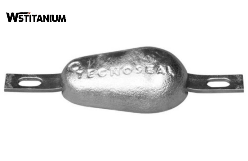
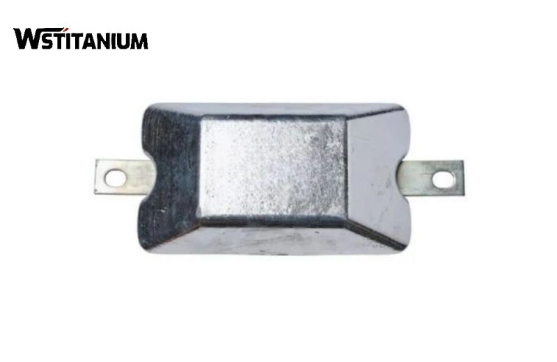
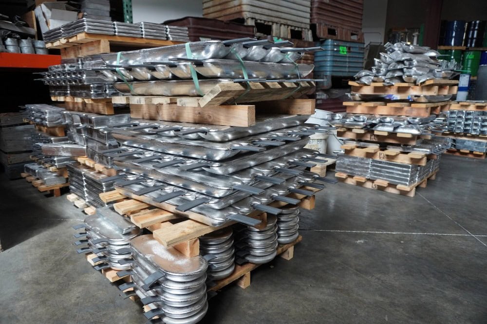
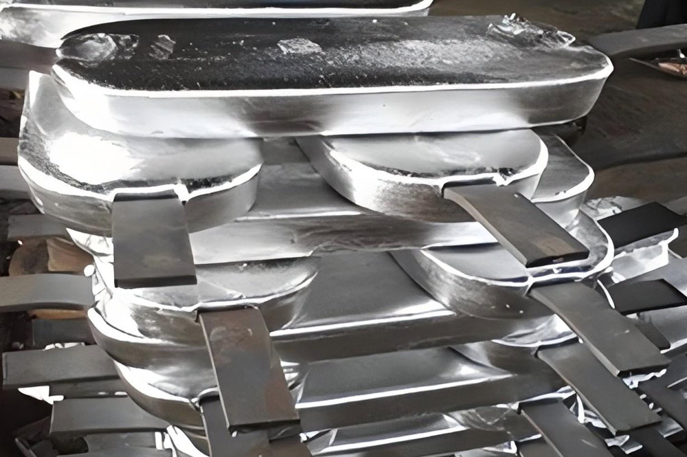
Anode Shape: Due to limited space beneath the tank bottom plate, flat, strip, and disc-shaped structures are used. Flat anodes have a thickness of 50-100mm, width of 150-300mm, and length of 500-2000mm, with a single anode weighing 5-50kg.
Core Performance of Zinc Anodes
According to ASTM B418-21 and ISO 19721:2017 standards, the core performance indicators of zinc sacrificial anodes for storage tanks must meet the following requirements:
- Theoretical Capacity: 820 Ah/kg, which is the theoretical maximum discharge capacity of the zinc anode;
- Current Efficiency: Seawater environment ≥90%, Soil/Freshwater environment ≥85%;
- Operating Potential: -1.00~-1.10V (vs CSE, at rated current density);
- Actual Capacity: Seawater environment ≥740 Ah/kg, Soil environment ≥700 Ah/kg, Freshwater ≥697 Ah/kg;
- Open Circuit Potential: -1.05~-1.15V (vs CSE, 25℃ standard environment);
- Dissolution: Uniform dissolution, without localized pitting or passivation;
Connection: The connection resistance between the anode and the cable ≤0.01Ω, and the sealing performance meets the requirement of no leakage at a water depth of 10m for 72 hours.
Calculation of Zinc Sacrificial Anode System In Storage Tank
The design of zinc sacrificial anode systems for storage tanks must strictly adhere to the three authoritative standards: API RP 651-2021, AMPP SP0193-2021, and ISO 19721:2017. The design process, parameter selection, and calculations must meet the specifications to ensure the long-term stability and effectiveness of the system.
Tank Body: Tank type (above ground/underground), volume, diameter, height, bottom plate area, wall protection area, tank material (carbon steel/low alloy steel), design pressure, design temperature;
Coating: Coating type, thickness, design service life, initial failure rate, estimated failure rate after years of operation (1%~5% for new tanks, 10%~20% for tanks over 10 years of operation);
Environment: Resistivity, pH value, chloride ion concentration, temperature, moisture content, SRB content, redox potential of the soil at the tank bottom/medium inside the tank;
Protective Current Density
Protective current density refers to the protective current required per unit area of the steel substrate. It is a core parameter in design calculations and must be considered based on the tank’s application scenario, corrosive environment, coating, and other factors. The authoritative standard recommends the following protective current densities:
| Storage Tank Application Scenario | Environment | Recommended Protection Current Density (mA/m²) | Reference Standard |
|---|---|---|---|
| Outside Bottom of Aboveground Storage Tank | Low Resistivity Soil (ρ < 500 Ω·cm) | 10-20 | AMPP SP0193-2021 |
| Outside Bottom of Aboveground Storage Tank | Medium Resistivity Soil (500 < ρ < 2000 Ω·cm) | 5-10 | AMPP SP0193-2021 |
| Aqueous Phase Inside Bottom of Crude Oil Storage Tank | High Cl⁻, SRB Anaerobic Environment | 20-50 | API RP 651-2021 |
| Inside of Drinking Water / Fire Water Storage Tank | Fresh Water / Neutral Environment | 5-10 | ANSI/NSF 61 |
| Inside of Seawater / Produced Water Storage Tank | High-Salt Corrosive Environment | 30-100 | ISO 12473:2017 |
| Oil-Water Interface Zone of Storage Tank Wall | Crude Oil / Product Oil Interface | 50-100 | Al-Mazeedi et al. (2019) |
| Underground Steel Storage Tank (UST) | Buried Soil + Groundwater Environment | 10-30 | AMPP SP0207-2022 |
← Swipe left/right to view full table →
Note: For every 5% increase in coating damage rate, the protective current density needs to be increased by 50%; in SRB breeding environments, the protective current density needs to be increased by 1 to 2 times; when the temperature exceeds 40℃, the protective current density needs to be increased by 50%.
Calculation of Total Protection Current
The total protection current is the sum of the current required for all protected areas of the storage tank, and the calculation formula is:
I_total = Σ(S_n × i_n × K)
Where:
I_total: Total protection current of the system, unit: Ampere (A);
S_n: Area of each protected area, unit: square meter (m²);
i_n: Corresponding protection current density of each protected area, unit: Ampere per square meter (A/m²);
K: Safety factor, with a value range of 1.2~1.5, which is used to cover uncertain factors such as coating aging, environmental changes and anode consumption.
Calculation of Total Anode Mass
The total anode mass is calculated based on the total protection current, design service life and anode performance parameters, with the calculation formula as follows:
W_total = (I_total × T × 8760) / (C × η × K_u)
Where:
W_total: Total required mass of zinc anode, unit: kilogram (kg);I_total: Total protection current of the system, unit: Ampere (A);T: Design service life of the system, unit: year (a);8760: Number of hours in one year;
C: Theoretical capacity of zinc anode, 820 Ah/kg;η: Anode current efficiency, 0.85 for soil/fresh water environment, 0.9 for seawater environment;K_u: Anode utilization rate, with a recommended value of 0.85. The anode is deemed invalid and unable to continue service when the remaining residual body of the anode reaches 15%.
Calculation of Anode Quantity
The total required number of anodes is calculated according to the rated mass of a single anode, with the calculation formula as follows:
N = W_total / W_0
Where:
N: Total number of anodes, unit: piece;W_total: Total mass of anodes, unit: kilogram (kg);W_0: Rated mass of a single anode, unit: kilogram per piece (kg/piece).
Anode Remaining Service Life Assessment
The remaining service life of the anode is the core indicator for evaluating the operating status of the system, which can be accurately calculated by the following formula:
T_remaining = (W_remaining × C × η × K_u) / (I_avg × 8760)
Where:
T_remaining: Remaining service life of the anode, unit: year (a);W_remaining: Total remaining mass of the anode, unit: kilogram (kg), which can be obtained by tank cleaning and weighing, or calculated via the service time and average output current;I_avg: Annual average output current of the anode, unit: Ampere (A), which is calculated from annual inspection data;C,η,K_u: Consistent with the parameters used in the design calculation.
When the remaining service life of the anode is less than 2 years, an anode replacement plan shall be formulated to avoid insufficient protection of the storage tank due to system failure. When the remaining service life of the anode is less than 1 year, the anode must be replaced immediately to ensure the continuous and effective operation of the system.
Conclusion
Zinc sacrificial anodes are a mature, reliable, and economical cathodic protection technology. They are a core component of corrosion protection systems for steel storage tanks and are widely used in various industries, including oil and gas, water utilities, chemicals, shipping ports, food and beverage, and mining. This guide outlines the technical system of zinc sacrificial anodes for storage tanks, covering material standards, electrochemical principles, and design selection. During the design phase, it is essential to accurately assess the corrosive environment of the storage tank and rationally select design parameters.
Reference
AMPP. (2021). SP0193-2021: Cathodic Protection of Aboveground Petroleum Storage Tank Bottoms. Association for Materials Protection and Performance.
AMPP. (2022). SP0207-2022: Cathodic Protection of Underground Storage Tanks (USTs). Association for Materials Protection and Performance.
AMPP. (2024). RP0175-2024: Control of Corrosion in Oil and Gas Production. Association for Materials Protection and Performance.
API. (2021). RP 651-2021: Cathodic Protection of Aboveground Storage Tanks. American Petroleum Institute.
API. (2023). API 650-2023: Welded Steel Tanks for Oil Storage. American Petroleum Institute.
ASTM International. (2021). B418-21: Standard Specification for Cast and Wrought Zinc Anodes for Cathodic Protection.
ASTM International. (2023). G8-18(2023): Standard Test Method for Cathodic Disbonding of Pipeline Coatings.
ISO. (2017). ISO 19721:2017: Petroleum and natural gas industries — Cathodic protection of aboveground storage tank bottoms.
ISO. (2017). ISO 12473:2017: Cathodic protection of metallic structures in seawater and marine environments.
ANSI/NSF. (2021). ANSI/NSF 61-2021: Drinking Water System Components – Health Effects. NSF International.
AWWA. (2020). AWWA D102-20: Cathodic Protection of Steel Water Tanks. American Water Works Association.
IMO. (2020). IMO Resolution MSC.216(82): Standards for Cathodic Protection of Ship’s Ballast Tanks. International Maritime Organization.
U.S. EPA. (2022). Underground Storage Tank (UST) Program: Technical Standards and Corrective Action Requirements.
Roberts, D. A., Gnanavelu, A., & Kain, R. (2021). Global Cost of Corrosion and the Role of Corrosion Management in Sustainable Development. npj Materials Degradation, 5(1), 11.
Bae, J., Lee, J., & Kim, Y. (2020). Effect of Temperature on the Electrochemical Behavior of Zinc Anodes for Cathodic Protection in Freshwater Environments. Corrosion Science, 174, 108832.
Al-Mazeedi, H., Al-Sulaiman, F., & Al-Ajmi, A. (2019). Cathodic Protection of Crude Oil Storage Tanks: A Comparative Study of Zinc and Aluminum Anodes. Journal of Pipeline Systems Engineering and Practice, 10(4), 04019024.
Zhang, Y., Wang, L., & Li, X. (2022). Long-Term Performance of Zinc Sacrificial Anodes in Buried Soil Environments: Field Testing and Numerical Simulation. Journal of Materials Engineering and Performance, 31(12), 9876-9889.
Shibli, S. M. A., & Remya, R. (2018). High Performance Zinc Anode with Modified Backfill Composition for Cathodic Protection of Buried Steel Structures. Construction and Building Materials, 175, 547-554.
Peabody, A. W., & Bianchetti, C. (2019). Peabody’s Control of Pipeline Corrosion (4th ed.). Association for Materials Protection and Performance.
Uhlig, H. H., & Revie, R. W. (2017). Uhlig’s Corrosion Handbook (3rd ed.). John Wiley & Sons.
